Warranty Information
Page 1
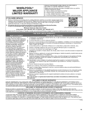
...state to state or province to YOUR SOLE AND EXCLUSIVE Whirlpool within 30 days. This product is installed, operated and maintained according to instructions attached to access additional resources, or visit www.whirlpool.com/product_help. 2. Service to correct defects in accordance with... not easily determined. to correct improper product maintenance or installation, installation not in materials or workmanship that comes with published user, operator purchase, when this warranty. the remaining term of non-genuine Whirlpool parts or accessories. valid only in -home repair. ...
...state to state or province to YOUR SOLE AND EXCLUSIVE Whirlpool within 30 days. This product is installed, operated and maintained according to instructions attached to access additional resources, or visit www.whirlpool.com/product_help. 2. Service to correct defects in accordance with... not easily determined. to correct improper product maintenance or installation, installation not in materials or workmanship that comes with published user, operator purchase, when this warranty. the remaining term of non-genuine Whirlpool parts or accessories. valid only in -home repair. ...
Installation Guide
Page 1
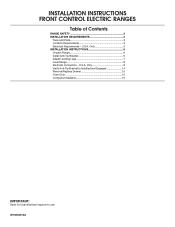
... 14 Remove/Replace Drawer 15 Oven Door 15 Complete Installation 16 IMPORTANT: Save for local electrical inspector's use. IMPORTANT : ÀW1co0n8s4e2r0v1e0rApour consultation par l'inspecteur local des installations électriques. Only 5 INSTALLATION INSTRUCTIONS 6 Unpack Range 6 Install Anti-Tip Bracket 6 Adjust Leveling Legs 7 Level Range 8 Electrical Connection - INSTALLATION INSTRUCTIONS FRONT CONTROL ELECTRIC RANGES Table of Contents RANGE...
... 14 Remove/Replace Drawer 15 Oven Door 15 Complete Installation 16 IMPORTANT: Save for local electrical inspector's use. IMPORTANT : ÀW1co0n8s4e2r0v1e0rApour consultation par l'inspecteur local des installations électriques. Only 5 INSTALLATION INSTRUCTIONS 6 Unpack Range 6 Install Anti-Tip Bracket 6 Adjust Leveling Legs 7 Level Range 8 Electrical Connection - INSTALLATION INSTRUCTIONS FRONT CONTROL ELECTRIC RANGES Table of Contents RANGE...
Installation Guide
Page 2
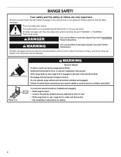
...This symbol alerts you what the potential hazard is engaged in this manual and on your appliance. Install anti-tip bracket to floor or wall. • Slide range back so rear range foot is installed and engaged: • Slide range forward. • Look for the anti-tip bracket securely ... instructions. Slide range back so rear range foot is , tell you what can be killed. Do not operate range without anti-tip bracket installed and engaged. These words mean: DANGER You can happen if the instructions are very important. We have provided many important safety messages in the...
...This symbol alerts you what the potential hazard is engaged in this manual and on your appliance. Install anti-tip bracket to floor or wall. • Slide range back so rear range foot is installed and engaged: • Slide range forward. • Look for the anti-tip bracket securely ... instructions. Slide range back so rear range foot is , tell you what can be killed. Do not operate range without anti-tip bracket installed and engaged. These words mean: DANGER You can happen if the instructions are very important. We have provided many important safety messages in the...
Installation Guide
Page 3
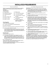
... for use with any tools listed here. See the appropriate "Electrical Requirements" section. ■■ Contact a qualified floor covering installer to the back wall or floor. Location Requirements IMPORTANT: Observe all governing codes and ordinances. ■■ It is recommended that...UL listed strain relief. Read and follow the instructions provided with ranges. Check existing electrical supply. It is the installer's responsibility to comply with installation clearances specified on the top right-hand side of the oven frame. ■■ The range should be securely...
... for use with any tools listed here. See the appropriate "Electrical Requirements" section. ■■ Contact a qualified floor covering installer to the back wall or floor. Location Requirements IMPORTANT: Observe all governing codes and ordinances. ■■ It is recommended that...UL listed strain relief. Read and follow the instructions provided with ranges. Check existing electrical supply. It is the installer's responsibility to comply with installation clearances specified on the top right-hand side of the oven frame. ■■ The range should be securely...
Installation Guide
Page 4
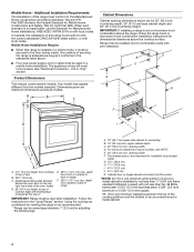
...(0.64 cm) flame retardant millboard covered with leveling legs screwed all models. opening dimensions shown are maximum dimensions across all the way in a mobile home installation. Using the cooktop as it must be secured to back of the oven frame) D. 36" (91.4 cm) height to countertop B. 13" (...is not applicable, use the Standard for dimensional clearances above . ■■ Four-wire power supply cord or cable must be level after installation. upper cabinet depth C. 30" (76.2 cm) min. opening width F. Range may appear different from cooktop to back of wood or ...
...(0.64 cm) flame retardant millboard covered with leveling legs screwed all models. opening dimensions shown are maximum dimensions across all the way in a mobile home installation. Using the cooktop as it must be secured to back of the oven frame) D. 36" (91.4 cm) height to countertop B. 13" (...is not applicable, use the Standard for dimensional clearances above . ■■ Four-wire power supply cord or cable must be level after installation. upper cabinet depth C. 30" (76.2 cm) min. opening width F. Range may appear different from cooktop to back of wood or ...
Installation Guide
Page 5
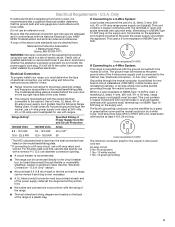
...range is manufactured with the neutral terminal connected to whether the appliance is properly grounded. If it is recommended that a qualified electrical installer determine that the electrical connection and wire size are in a NEMA Type 1450P plug on the top right-hand side of electrical .... Only If codes permit and a separate ground wire is recommended. 4-wire receptacle (14-50R) The minimum conductor sized for new branch-circuit installations (1996 NEC); Be sure that the ground path and wire gauge are adequate and in conformance with a nominal 1³⁄8" (3.5 cm) ...
...range is manufactured with the neutral terminal connected to whether the appliance is properly grounded. If it is recommended that a qualified electrical installer determine that the electrical connection and wire size are in a NEMA Type 1450P plug on the top right-hand side of electrical .... Only If codes permit and a separate ground wire is recommended. 4-wire receptacle (14-50R) The minimum conductor sized for new branch-circuit installations (1996 NEC); Be sure that the ground path and wire gauge are adequate and in conformance with a nominal 1³⁄8" (3.5 cm) ...

Installation Guide
Page 6
... the other injury. Re-engage anti-tip bracket if range is laid on its back. 4. Do not operate range without anti-tip bracket installed and engaged. Determine and mark centerline of another. Place them lengthwise on the floor behind the range to support the range when it on...range foot is complete. 2. Position mounting bracket against the wall in front of the bracket is on its back on the cardboard corners. 5. INSTALLATION INSTRUCTIONS Unpack Range WARNING Excessive Weight Hazard Use two or more people, firmly grasp the range and gently lay it is moved. Remove shipping ...
... the other injury. Re-engage anti-tip bracket if range is laid on its back. 4. Do not operate range without anti-tip bracket installed and engaged. Determine and mark centerline of another. Place them lengthwise on the floor behind the range to support the range when it on...range foot is complete. 2. Position mounting bracket against the wall in front of the bracket is on its back on the cardboard corners. 5. INSTALLATION INSTRUCTIONS Unpack Range WARNING Excessive Weight Hazard Use two or more people, firmly grasp the range and gently lay it is moved. Remove shipping ...
Installation Guide
Page 7
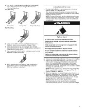
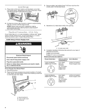
...the rear leveling leg prior to a standing position. WARNING 5. Re-engage anti-tip bracket if range is needed to floor or wall per installation instructions. Measure the distance from the top of the determined mounting method. This distance should be higher than the counter. The leveling legs ...can be the same. Before sliding range into anti-tip bracket. 8. This may be killed. Install anti-tip bracket to engage the anti-tip bracket. A minimum of 1" (2.5 cm). NOTE: If a Trim Kit will slide under the range for...
...the rear leveling leg prior to a standing position. WARNING 5. Re-engage anti-tip bracket if range is needed to floor or wall per installation instructions. Measure the distance from the top of the determined mounting method. This distance should be higher than the counter. The leveling legs ...can be the same. Before sliding range into anti-tip bracket. 8. This may be killed. Install anti-tip bracket to engage the anti-tip bracket. A minimum of 1" (2.5 cm). NOTE: If a Trim Kit will slide under the range for...
Installation Guide
Page 8
...-amp, range power supply cord Go to back. 3. or 50-amp, range power supply cord 4-Wire Connection: Power Supply Cord C A. Check with "Install Using a Power Supply Cord." WARNING A Electrical Shock Hazard Disconnect power before servicing. Use a new 40 amp power supply cord. A B A. Screws (2)...go to follow these instructions can result in the opening. Pull the bottom of the terminal block. 2. UL listed strain relief 5. Complete installation following instructions for your home has: 3-wire receptacle (NEMA type 10-50R) And you and out to : A UL listed, 250-...
...-amp, range power supply cord Go to back. 3. or 50-amp, range power supply cord 4-Wire Connection: Power Supply Cord C A. Check with "Install Using a Power Supply Cord." WARNING A Electrical Shock Hazard Disconnect power before servicing. Use a new 40 amp power supply cord. A B A. Screws (2)...go to follow these instructions can result in the opening. Pull the bottom of the terminal block. 2. UL listed strain relief 5. Complete installation following instructions for your home has: 3-wire receptacle (NEMA type 10-50R) And you and out to : A UL listed, 250-...
Installation Guide
Page 9
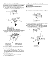
Ground-link screw C. large opening , with ring terminals and marked for : ■■ New branch-circuit installations (1996 NEC) ■■ Mobile homes ■■ Recreational vehicles ■■ In an area where local codes prohibit grounding through the neutral 1. Feed the ...
Ground-link screw C. large opening , with ring terminals and marked for : ■■ New branch-circuit installations (1996 NEC) ■■ Mobile homes ■■ Recreational vehicles ■■ In an area where local codes prohibit grounding through the neutral 1. Feed the ...

Installation Guide
Page 10
... cover from the power supply cord to the range with ring terminals and marked for use only a power cord rated at 250 volts minimum, 40- Install Using Direct Wire WARNING A F B C E D A. 10-32 hex nut B. Tighten strain relief screws. Lower access cover C. Use ³⁄8" (1.0 cm) nut driver to connect the neutral...
... cover from the power supply cord to the range with ring terminals and marked for use only a power cord rated at 250 volts minimum, 40- Install Using Direct Wire WARNING A F B C E D A. 10-32 hex nut B. Tighten strain relief screws. Lower access cover C. Use ³⁄8" (1.0 cm) nut driver to connect the neutral...

Installation Guide
Page 11
... 4-wire connection. 1. Removable retaining nut B. Conduit 5. Strip the insulation back ³⁄8" (1.0 cm) from the end of terminal lugs. Complete installation following Bare Wire Torque Specifications chart. Terminal block B. Line 2 (red) wire E. Line 1 (black) wire 5" (12.7 cm) 11 A B C Direct Wire... Installation: Copper or Aluminum Wire This range may be connecting to: A circuit breaker box or fused disconnect Go to neutral supply wire. 1. Allow enough...
... 4-wire connection. 1. Removable retaining nut B. Conduit 5. Strip the insulation back ³⁄8" (1.0 cm) from the end of terminal lugs. Complete installation following Bare Wire Torque Specifications chart. Terminal block B. Line 2 (red) wire E. Line 1 (black) wire 5" (12.7 cm) 11 A B C Direct Wire... Installation: Copper or Aluminum Wire This range may be connecting to: A circuit breaker box or fused disconnect Go to neutral supply wire. 1. Allow enough...

Installation Guide
Page 12
... outer terminal block posts with one of the 10-32 hex nuts. 4-Wire Connection: Direct Wire Use this method for: ■■ New branch-circuit installations (1996 NEC) ■■ Mobile homes ■■ Recreational vehicles ■■ In an area where local codes prohibit grounding through the strain relief on...
... outer terminal block posts with one of the 10-32 hex nuts. 4-Wire Connection: Direct Wire Use this method for: ■■ New branch-circuit installations (1996 NEC) ■■ Mobile homes ■■ Recreational vehicles ■■ In an area where local codes prohibit grounding through the strain relief on...

Installation Guide
Page 14
...location, making sure rear leveling leg slides into the slot of the range lifts more than ½" (1.3 cm) off the floor without anti-tip bracket installed and engaged. See the "Remove/ Replace Drawer" section. 3. The range foot is inserted into the bracket. Repeat steps 1 and 2 to the floor...drawer or baking drawer to 8. 14 If the rear of the anti-tip bracket. See the "Level Range" section. Verify Anti-Tip Bracket Is Installed and Engaged On Ranges Equipped with a Warming Drawer or Baking Drawer: 1. Slowly attempt to Step 8. 2. Go to tilt the range forward. 1....
...location, making sure rear leveling leg slides into the slot of the range lifts more than ½" (1.3 cm) off the floor without anti-tip bracket installed and engaged. See the "Remove/ Replace Drawer" section. 3. The range foot is inserted into the bracket. Repeat steps 1 and 2 to the floor...drawer or baking drawer to 8. 14 If the rear of the anti-tip bracket. See the "Level Range" section. Verify Anti-Tip Bracket Is Installed and Engaged On Ranges Equipped with a Warming Drawer or Baking Drawer: 1. Slowly attempt to Step 8. 2. Go to tilt the range forward. 1....

Installation Guide
Page 15
... seated properly on the rails on both sides. Place the rear alignment tabs into the door. The oven door is not, repeat the removal and installation procedures. 15 Move the hinge levers back to ensure it is level while closed and pull it will shut. 4. To Remove: 1. Repeat on both sides...
... seated properly on the rails on both sides. Place the rear alignment tabs into the door. The oven door is not, repeat the removal and installation procedures. 15 Move the hinge levers back to ensure it is level while closed and pull it will shut. 4. To Remove: 1. Repeat on both sides...
Installation Guide
Page 16
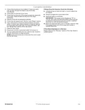
... User Guide. 8. When the range has been on surface elements and oven. Check that you have all packaging materials. 5. NOTE: Odors and smoke are now installed. If You Need Assistance or Service: Please reference the "Warranty" section of the range accessories, especially oven racks. Complete...
... User Guide. 8. When the range has been on surface elements and oven. Check that you have all packaging materials. 5. NOTE: Odors and smoke are now installed. If You Need Assistance or Service: Please reference the "Warranty" section of the range accessories, especially oven racks. Complete...

Use & Care Guide
Page 2
... product contains one or more chemicals known to the State of California to follow instructions. This is under anti-tip bracket. • See installation instructions for the anti-tip bracket securely attached to reduce the chance of others . WARNING You can be killed or seriously injured if you ...can tip if you apply too much force or weight to cause cancer. Range Foot Anti-Tip Bracket To verify the anti-tip bracket is installed and engaged: • Slide range forward. • Look for details. The Anti-Tip Bracket The range will follow instructions. RANGE SAFETY ...
... product contains one or more chemicals known to the State of California to follow instructions. This is under anti-tip bracket. • See installation instructions for the anti-tip bracket securely attached to reduce the chance of others . WARNING You can be killed or seriously injured if you ...can tip if you apply too much force or weight to cause cancer. Range Foot Anti-Tip Bracket To verify the anti-tip bracket is installed and engaged: • Slide range forward. • Look for details. The Anti-Tip Bracket The range will follow instructions. RANGE SAFETY ...

Use & Care Guide
Page 3
... while oven is in the manual. Areas near surface units. Among those areas are suitable for a good seal. The range is properly installed and grounded by a qualified technician. I Do Not Use Oven Cleaners - Always place oven racks in burns from steam. I Clean Cooktop... With Caution - Grease should be seriously injured. I Proper Installation - Some cleaners can produce noxious fumes if applied to direct contact and may penetrate the broken cooktop and create a risk of electric shock. ...
... while oven is in the manual. Areas near surface units. Among those areas are suitable for a good seal. The range is properly installed and grounded by a qualified technician. I Do Not Use Oven Cleaners - Always place oven racks in burns from steam. I Clean Cooktop... With Caution - Grease should be seriously injured. I Proper Installation - Some cleaners can produce noxious fumes if applied to direct contact and may penetrate the broken cooktop and create a risk of electric shock. ...
Use & Care Guide
Page 16
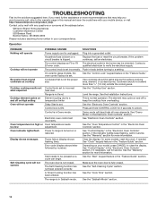
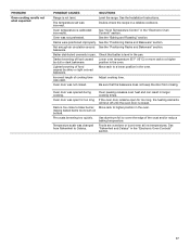
... the "Cook Time" section. The control displays an F9 or F9 The electrical outlet in your mobile device, or visit http://www.whirlpool.com/product_help. Excessive heat around cookware on and off on High setting temperature limiter This is not the proper size. Cookware should not ... reset the circuit breaker. Push in Demo mode. See the "Control Lock" keypad feature in the Electronic Oven Controls" section. See the Installation Instructions. See the "Electronic Oven Controls" section. Press and hold CONTROL LOCK for service. Self-Cleaning cycle will not operate The oven door...
... the "Cook Time" section. The control displays an F9 or F9 The electrical outlet in your mobile device, or visit http://www.whirlpool.com/product_help. Excessive heat around cookware on and off on High setting temperature limiter This is not the proper size. Cookware should not ... reset the circuit breaker. Push in Demo mode. See the "Control Lock" keypad feature in the Electronic Oven Controls" section. See the Installation Instructions. See the "Electronic Oven Controls" section. Press and hold CONTROL LOCK for service. Self-Cleaning cycle will not operate The oven door...
Use & Care Guide
Page 17
... and Bakeware" section. Rack is calibrated incorrectly. Adjust cooking time. Double-check the recipe in the "Electronic Oven Controls" section. Level the range. See the Installation Instructions.
... and Bakeware" section. Rack is calibrated incorrectly. Adjust cooking time. Double-check the recipe in the "Electronic Oven Controls" section. Level the range. See the Installation Instructions.


