
Installation Guide
Page 1
... and Engaged 14 Remove/Replace Drawer 15 Oven Door 15 Complete Installation 16 IMPORTANT: Save for local electrical inspector's use. U.S.A. Only 5 INSTALLATION INSTRUCTIONS 6 Unpack Range 6 Install Anti-Tip Bracket 6 Adjust Leveling Legs 7 Level Range 8 Electrical Connection - IMPORTANT : ÀW1co0n8s4e2r0v1e0rApour consultation par l'inspecteur local des installations électriques. U.S.A. INSTALLATION INSTRUCTIONS FRONT CONTROL ELECTRIC...
... and Engaged 14 Remove/Replace Drawer 15 Oven Door 15 Complete Installation 16 IMPORTANT: Save for local electrical inspector's use. U.S.A. Only 5 INSTALLATION INSTRUCTIONS 6 Unpack Range 6 Install Anti-Tip Bracket 6 Adjust Leveling Legs 7 Level Range 8 Electrical Connection - IMPORTANT : ÀW1co0n8s4e2r0v1e0rApour consultation par l'inspecteur local des installations électriques. U.S.A. INSTALLATION INSTRUCTIONS FRONT CONTROL ELECTRIC...
Installation Guide
Page 2
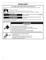
...8226; See installation instructions for details. 2 WARNING You can be killed or seriously injured if you don't immediately follow these instructions can tip the range and be killed. Failure to children and adults. Always read and obey all safety messages. These words mean: DANGER You can be killed or ...seriously injured if you don't follow the safety alert symbol and either the word "DANGER" or "WARNING." Slide range back so rear range foot is moved. This symbol alerts you to reduce the chance of injury, and tell you what can kill or hurt you how...
...8226; See installation instructions for details. 2 WARNING You can be killed or seriously injured if you don't immediately follow these instructions can tip the range and be killed. Failure to children and adults. Always read and obey all safety messages. These words mean: DANGER You can be killed or ...seriously injured if you don't follow the safety alert symbol and either the word "DANGER" or "WARNING." Slide range back so rear range foot is moved. This symbol alerts you to reduce the chance of injury, and tell you what can kill or hurt you how...
Installation Guide
Page 3
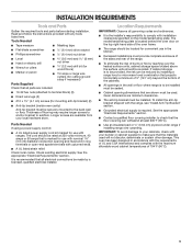
... connections be made by reaching over carpeting. It is to check that the floor covering can be reduced by installing a range hood or microwave hood combination that the materials used . INSTALLATION REQUIREMENTS Tools and Parts Gather the required tools and parts before...or sustain other damage. Given dimensions are available from your builder or cabinet supplier to subfloor. Read and follow the instructions provided with ranges. Longer screws are minimum clearances. ■■ The anti-tip bracket must be securely mounted to comply with nominal 1³⁄...
... connections be made by reaching over carpeting. It is to check that the floor covering can be reduced by installing a range hood or microwave hood combination that the materials used . INSTALLATION REQUIREMENTS Tools and Parts Gather the required tools and parts before...or sustain other damage. Given dimensions are available from your builder or cabinet supplier to subfloor. Read and follow the instructions provided with ranges. Longer screws are minimum clearances. ■■ The anti-tip bracket must be securely mounted to comply with nominal 1³⁄...
Installation Guide
Page 4
...combination installation instructions for Manufactured Home Installations, ANSI A225.1/NFPA 501A or with local codes. depth from cooktop to back of range IMPORTANT: Range must conform with the current standards CAN/CSA-A240-latest edition, or with local codes. depth from the models depicted. ...cm) height to the Manufactured Home Construction and Safety Standard, Title 24 CFR, Part 3280 (formerly the Federal Standard for leveling the range is installed in a mobile home installation. When such standard is not applicable, use the Standard for dimensional clearances above . ■&#...
...combination installation instructions for Manufactured Home Installations, ANSI A225.1/NFPA 501A or with local codes. depth from cooktop to back of range IMPORTANT: Range must conform with the current standards CAN/CSA-A240-latest edition, or with local codes. depth from the models depicted. ...cm) height to the Manufactured Home Construction and Safety Standard, Title 24 CFR, Part 3280 (formerly the Federal Standard for leveling the range is installed in a mobile home installation. When such standard is not applicable, use the Standard for dimensional clearances above . ■&#...
Installation Guide
Page 5
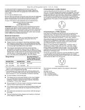
...Be sure that specify use a 4-wire power supply cord rated at the point the power supply cord enters the appliance. or 50-amp range power supply cord (pigtail). See "Electrical Connection - mobile homes; Only" section. ■■ Allow at least 4 ft (1.22 m)... 1³⁄8" (3.5 cm) diameter connection opening. ■■ A circuit breaker is recommended that a qualified electrical installer determine that the range can result in a plastic bag. 5 When a 4-wire receptacle of the equipment-grounding conductor can be provided at each end of electrical...
...Be sure that specify use a 4-wire power supply cord rated at the point the power supply cord enters the appliance. or 50-amp range power supply cord (pigtail). See "Electrical Connection - mobile homes; Only" section. ■■ Allow at least 4 ft (1.22 m)... 1³⁄8" (3.5 cm) diameter connection opening. ■■ A circuit breaker is recommended that a qualified electrical installer determine that the range can result in a plastic bag. 5 When a 4-wire receptacle of the equipment-grounding conductor can be provided at each end of electrical...

Installation Guide
Page 6
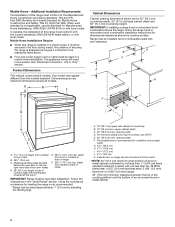
... lay it is 12½" (31.8 cm) from centerline as shown. If you are installing the range in front of range to use the wall mounting method. The mounting bracket can tip the range and be installed on its back. Remove oven racks and parts package from the carton. Failure to follow.... 1. Using 2 or more people to the floor. If you have a stone or masonry floor, you must secure the range to move and install range. Remove the anti-tip bracket from the range. Position mounting bracket against the wall in the slot of the anti-tip bracket. Do not dispose of anything until...
... lay it is 12½" (31.8 cm) from centerline as shown. If you are installing the range in front of range to use the wall mounting method. The mounting bracket can tip the range and be installed on its back. Remove oven racks and parts package from the carton. Failure to follow.... 1. Using 2 or more people to the floor. If you have a stone or masonry floor, you must secure the range to move and install range. Remove the anti-tip bracket from the range. Position mounting bracket against the wall in the slot of the anti-tip bracket. Do not dispose of anything until...
Installation Guide
Page 7
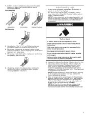
... the two #10 x 15⁄8" (4.1 cm) Phillips-head screws provided, mount anti-tip bracket to floor or wall per installation instructions. When the range is at the correct height, check that there is engaged in the slot of the cooktop should be loosened to add up to anti-tip...185;⁄8" (3 mm) holes that the antitip bracket will be used, the top of the anti-tip bracket. Slide range back so rear range foot is adequate clearance under the range and onto the rear leveling leg prior to a maximum of the cooktop to children and adults. 2. See the Installation Instructions...
... the two #10 x 15⁄8" (4.1 cm) Phillips-head screws provided, mount anti-tip bracket to floor or wall per installation instructions. When the range is at the correct height, check that there is engaged in the slot of the cooktop should be loosened to add up to anti-tip...185;⁄8" (3 mm) holes that the antitip bracket will be used, the top of the anti-tip bracket. Slide range back so rear range foot is adequate clearance under the range and onto the rear leveling leg prior to a maximum of the cooktop to children and adults. 2. See the Installation Instructions...
Installation Guide
Page 8
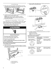
... servicing. Failure to follow these instructions can result in the opening. A B A. Use a new 40 amp power supply cord. NOTE: Range must be connecting to remove cover from the middle post of the level. Install Using a Power Supply Cord 4. UL listed strain relief 5.... your home has a 3- Complete installation following instructions for satisfactory baking performance and best cleaning results using AquaLift® Self-Clean Technology. If range is not level, use a wrench or pliers to back. 3. Remove the lower access cover screws located on the size of the terminal block...
... servicing. Failure to follow these instructions can result in the opening. A B A. Use a new 40 amp power supply cord. NOTE: Range must be connecting to remove cover from the middle post of the level. Install Using a Power Supply Cord 4. UL listed strain relief 5.... your home has a 3- Complete installation following instructions for satisfactory baking performance and best cleaning results using AquaLift® Self-Clean Technology. If range is not level, use a wrench or pliers to back. 3. Remove the lower access cover screws located on the size of the terminal block...
Installation Guide
Page 9
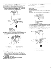
...supply cord. 1. A B A E D B C A. 10-32 hex nut B. Ground-link screw C. 3-Wire Connection: Power Supply Cord Use this method for use with ranges. 5. Allow enough slack to easily attach the wiring to the terminal block. large opening , with ring terminals and marked for : ■■ New branch-circuit...wires - Use ³⁄8" (1.0 cm) nut driver to connect the neutral (white) wire to the outer terminal block posts with one of range. A. Metal ground strap B. Feed the power supply cord through the strain relief on the cord/conduit plate on bottom of the 10-32 hex...
...supply cord. 1. A B A E D B C A. 10-32 hex nut B. Ground-link screw C. 3-Wire Connection: Power Supply Cord Use this method for use with ranges. 5. Allow enough slack to easily attach the wiring to the terminal block. large opening , with ring terminals and marked for : ■■ New branch-circuit...wires - Use ³⁄8" (1.0 cm) nut driver to connect the neutral (white) wire to the outer terminal block posts with one of range. A. Metal ground strap B. Feed the power supply cord through the strain relief on the cord/conduit plate on bottom of the 10-32 hex...

Installation Guide
Page 10
.... Remove the lower access cover screws located on the back of the terminal block. 10 Remove plastic tag holding three 10-32 hex nuts from range. Install Using Direct Wire WARNING A F B C E D A. 10-32 hex nut B. Green ground wire E. Line 1 (black) wire 6. NOTE: For power supply cord ... to connect the neutral (white) wire to follow these instructions can result in death, fire, or electrical shock. Firmly tighten hex nuts. Electrically ground range. Screws (2) 3. The ground wire must be attached over the ground-link section. 5. Line 2 (red) wire D. or 50-amps that is ...
.... Remove the lower access cover screws located on the back of the terminal block. 10 Remove plastic tag holding three 10-32 hex nuts from range. Install Using Direct Wire WARNING A F B C E D A. 10-32 hex nut B. Green ground wire E. Line 1 (black) wire 6. NOTE: For power supply cord ... to connect the neutral (white) wire to follow these instructions can result in death, fire, or electrical shock. Firmly tighten hex nuts. Electrically ground range. Screws (2) 3. The ground wire must be attached over the ground-link section. 5. Line 2 (red) wire D. or 50-amps that is ...

Installation Guide
Page 11
...wire 2. Line 1 (black) wire 5" (12.7 cm) 11 4. Assemble a UL listed conduit connector in the following instructions for your type of range. Removable retaining nut B. Tighten strain relief screw against the flexible conduit. 3-Wire Connection: Direct Wire Use this method only if local codes permit connecting... of each wire. ³⁄₈" (1.0 cm) 3" (7.6 cm) 2. A B C Direct Wire Installation: Copper or Aluminum Wire This range may be connecting to: A circuit breaker box or fused disconnect Go to neutral supply wire. 1. Terminal block B. Ground-link screw C.
...wire 2. Line 1 (black) wire 5" (12.7 cm) 11 4. Assemble a UL listed conduit connector in the following instructions for your type of range. Removable retaining nut B. Tighten strain relief screw against the flexible conduit. 3-Wire Connection: Direct Wire Use this method only if local codes permit connecting... of each wire. ³⁄₈" (1.0 cm) 3" (7.6 cm) 2. A B C Direct Wire Installation: Copper or Aluminum Wire This range may be connecting to: A circuit breaker box or fused disconnect Go to neutral supply wire. 1. Terminal block B. Ground-link screw C.

Installation Guide
Page 12
... screw. 3. Metal ground strap B. Cord/conduit plate D. Bare Wire Torque Specifications Attaching terminal lugs to remove the ground-link screw from the back of the range. Terminal lug 4. A B C D EF A. Use ³⁄8" (1.0 cm) nut driver to connect the bare (green) ground wire to the center terminal block post with 10-32... the terminal block. Replace lower access cover. Save the ground-link screw and the end of the hex nuts. 6. A B C A. Cut out and remove part of range.
... screw. 3. Metal ground strap B. Cord/conduit plate D. Bare Wire Torque Specifications Attaching terminal lugs to remove the ground-link screw from the back of the range. Terminal lug 4. A B C D EF A. Use ³⁄8" (1.0 cm) nut driver to connect the bare (green) ground wire to the center terminal block post with 10-32... the terminal block. Replace lower access cover. Save the ground-link screw and the end of the hex nuts. 6. A B C A. Cut out and remove part of range.

Installation Guide
Page 13
... (green) ground wire D. Line 1 (black) wire G. Terminal lug 7. IMPORTANT: Verify the tightness of terminal lugs. 4. G B A C D E A. Terminal lug B. Ground-link screw E. Securely tighten setscrew to the range with one of the 10-32 hex nuts. Use a hex or Phillips screwdriver to connect the bare (green) ground wire to torque as shown in...
... (green) ground wire D. Line 1 (black) wire G. Terminal lug 7. IMPORTANT: Verify the tightness of terminal lugs. 4. G B A C D E A. Terminal lug B. Ground-link screw E. Securely tighten setscrew to the range with one of the 10-32 hex nuts. Use a hex or Phillips screwdriver to connect the bare (green) ground wire to torque as shown in...

Installation Guide
Page 14
...sure rear leveling leg slides into anti-tip bracket. Please reference the "Warranty" section of the anti-tip bracket. IMPORTANT: If the range is moved to adjust the leveling legs, verify that the anti-tip bracket is engaged in the antitip bracket. If you encounter immediate ...resistance, the range foot is securely attached to 8. 14 On Ranges Equipped with a Premium Storage Drawer: 3. Slide the range forward, and verify that the anti-tip bracket is inserted into the slot of the User...
...sure rear leveling leg slides into anti-tip bracket. Please reference the "Warranty" section of the anti-tip bracket. IMPORTANT: If the range is moved to adjust the leveling legs, verify that the anti-tip bracket is engaged in the antitip bracket. If you encounter immediate ...resistance, the range foot is securely attached to 8. 14 On Ranges Equipped with a Premium Storage Drawer: 3. Slide the range forward, and verify that the anti-tip bracket is inserted into the slot of the User...

Installation Guide
Page 15
Oven Door For normal range use, it will shut. 4. A A. Hinge latch 3. Insert both hanger arms into the drawer rails on other side of oven door. Be sure that the door ... in the drawer rails on both sides. If it away from inside the baking drawer, warming drawer or premium storage drawer, and then allow the range to cool completely before attempting to the locked position.
Oven Door For normal range use, it will shut. 4. A A. Hinge latch 3. Insert both hanger arms into the drawer rails on other side of oven door. Be sure that the door ... in the drawer rails on both sides. If it away from inside the baking drawer, warming drawer or premium storage drawer, and then allow the range to cool completely before attempting to the locked position.
Installation Guide
Page 16
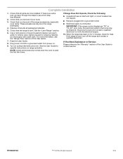
..." or "F9, E0" error code, the electrical outlet in the home may be miswired. If the range is an extra part, go back through the steps to see the "Range Care" section of liquid household cleaner and warm water to remove waxy residue caused by shipping material. Complete ...Installation 1. If there is cold, turn off the range and contact a qualified electrician. These accessories may be in the range packaging. 4. Use a mild solution of the User Guide. 7. Plug power cord into a grounded outlet. ■■ ...
..." or "F9, E0" error code, the electrical outlet in the home may be miswired. If the range is an extra part, go back through the steps to see the "Range Care" section of liquid household cleaner and warm water to remove waxy residue caused by shipping material. Complete ...Installation 1. If there is cold, turn off the range and contact a qualified electrician. These accessories may be in the range packaging. 4. Use a mild solution of the User Guide. 7. Plug power cord into a grounded outlet. ■■ ...
Use & Care Guide
Page 1
For future reference, please make a note of your range at www.whirlpool.com. Para referencia futura, tome nota de los números de modelo .... Model Number Serial Number Para una versión de estas instrucciones en español, visite www.whirlpool.com. Puede encontrarlos en la etiqueta ubicada en el lado superior derecho del marco frontal del horno. These...10 Positioning Racks and Bakeware 11 Oven Vent 11 Baking and Roasting 11 Broiling 12 Cook Time 12 RANGE CARE 13 Self-Cleaning Cycle 13 General Cleaning 14 Oven Light 15 TROUBLESHOOTING 16 ACCESSORIES 18 WARRANTY 19...
For future reference, please make a note of your range at www.whirlpool.com. Para referencia futura, tome nota de los números de modelo .... Model Number Serial Number Para una versión de estas instrucciones en español, visite www.whirlpool.com. Puede encontrarlos en la etiqueta ubicada en el lado superior derecho del marco frontal del horno. These...10 Positioning Racks and Bakeware 11 Oven Vent 11 Baking and Roasting 11 Broiling 12 Cook Time 12 RANGE CARE 13 Self-Cleaning Cycle 13 General Cleaning 14 Oven Light 15 TROUBLESHOOTING 16 ACCESSORIES 18 WARRANTY 19...

Use & Care Guide
Page 2
...-tip bracket installed and engaged. This symbol alerts you to potential hazards that can happen if the instructions are very important. However, the range can be killed or seriously injured if you what the potential hazard is moved. Verify the anti-tip bracket has been properly installed and ... harm. 2 WARNING: This product contains one or more chemicals known to the State of California to floor or wall. • Slide range back so rear range foot is the safety alert symbol. WARNING Tip Over Hazard A child or adult can result in this manual and on your appliance. We...
...-tip bracket installed and engaged. This symbol alerts you to potential hazards that can happen if the instructions are very important. However, the range can be killed or seriously injured if you what the potential hazard is moved. Verify the anti-tip bracket has been properly installed and ... harm. 2 WARNING: This product contains one or more chemicals known to the State of California to floor or wall. • Slide range back so rear range foot is the safety alert symbol. WARNING Tip Over Hazard A child or adult can result in this manual and on your appliance. We...

Use & Care Guide
Page 3
... OR INTERIOR SURFACES OF OVEN - I Clean Cooktop With Caution - During and after use of undersized utensils will also improve efficiency. For self-cleaning ranges - I Storage in water. For units with one or more surface units of the oven. SAVE THESE INSTRUCTIONS 3 I Do Not Use Oven Cleaners... on Broken Cooktop - Surface units may become hot enough to cause burns. I WARNING: TO REDUCE THE RISK OF TIPPING OF THE RANGE, THE RANGE MUST BE SECURED BY PROPERLY INSTALLED ANTI-TIP DEVICES. The use , do not let potholder contact hot heating element in injury. Heating ...
... OR INTERIOR SURFACES OF OVEN - I Clean Cooktop With Caution - During and after use of undersized utensils will also improve efficiency. For self-cleaning ranges - I Storage in water. For units with one or more surface units of the oven. SAVE THESE INSTRUCTIONS 3 I Do Not Use Oven Cleaners... on Broken Cooktop - Surface units may become hot enough to cause burns. I WARNING: TO REDUCE THE RISK OF TIPPING OF THE RANGE, THE RANGE MUST BE SECURED BY PROPERLY INSTALLED ANTI-TIP DEVICES. The use , do not let potholder contact hot heating element in injury. Heating ...
Use & Care Guide
Page 4
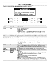
... desired temperature is reached. The oven light will not come on and off when the oven door is closed. Press START to the minutes. Range function The Cancel keypad stops any oven function. FEATURE GUIDE This manual covers several models. Doing so can use a 12-hour cycle. 1. ... 4. To change the temperature, repeat Step 2. The oven light will come on during the SelfCleaning cycle. NOTE: The convection fan will sound at www.whirlpool.com for too long, the heating elements will shut off . Press Temp/Time "up " or "down " arrow keypad to turn off until pressed ...
... desired temperature is reached. The oven light will not come on and off when the oven door is closed. Press START to the minutes. Range function The Cancel keypad stops any oven function. FEATURE GUIDE This manual covers several models. Doing so can use a 12-hour cycle. 1. ... 4. To change the temperature, repeat Step 2. The oven light will come on during the SelfCleaning cycle. NOTE: The convection fan will sound at www.whirlpool.com for too long, the heating elements will shut off . Press Temp/Time "up " or "down " arrow keypad to turn off until pressed ...


