
Dimension Guide
Page 1
...- The total length of 3 Dimensions are required. Dryer on both sides of the exhaust. Do not use an extension cord. Ref. Because Whirlpool Corporation policy includes a continuous commitment to improve our ...products, we reserve the right to change materials and specifications without notice. Page 1 of flexible metal vent should not exceed 7-3/4 ft. (2.4 m). ® Electric Dryer PRODUCT MODEL NUMBERS WED9200S WED9300V WED9400S WED9400V WED9500T WED9600T PRODUCT DIMENSIONS ELECTRICAL This dryer...
...- The total length of 3 Dimensions are required. Dryer on both sides of the exhaust. Do not use an extension cord. Ref. Because Whirlpool Corporation policy includes a continuous commitment to improve our ...products, we reserve the right to change materials and specifications without notice. Page 1 of flexible metal vent should not exceed 7-3/4 ft. (2.4 m). ® Electric Dryer PRODUCT MODEL NUMBERS WED9200S WED9300V WED9400S WED9400V WED9500T WED9600T PRODUCT DIMENSIONS ELECTRICAL This dryer...

Dimension Guide
Page 2
...76 mm) 1"* (25 mm) A* 1" 27" 1" (25 mm) (686 mm) (25 mm) Because Whirlpool Corporation policy includes a continuous commitment to change materials and specifications without notice. RECOMMENDED INSTALLATION SPACING FOR RECESSED OR CLOSET INSTALLATION, WITH ...spacing is allowed. Specifications subject to improve Dimensions are for cabinet installation. ® Electric Dryer PRODUCT MODEL NUMBERS WED9200S WED9300V WED9400S WED9400V WED9500T WED9600T RECOMMENDED INSTALLATION SPACING FOR CABINET INSTALLATION NOTE: Some models are not recommended for planning purposes only....
...76 mm) 1"* (25 mm) A* 1" 27" 1" (25 mm) (686 mm) (25 mm) Because Whirlpool Corporation policy includes a continuous commitment to change materials and specifications without notice. RECOMMENDED INSTALLATION SPACING FOR RECESSED OR CLOSET INSTALLATION, WITH ...spacing is allowed. Specifications subject to improve Dimensions are for cabinet installation. ® Electric Dryer PRODUCT MODEL NUMBERS WED9200S WED9300V WED9400S WED9400V WED9500T WED9600T RECOMMENDED INSTALLATION SPACING FOR CABINET INSTALLATION NOTE: Some models are not recommended for planning purposes only....

Dimension Guide
Page 3
EXHAUST VENTING A and B: Recommended hood styles. To determine maximum exhaust length, add one 90º turn inside the dryer. Plan the installation to the chart. Because Whirlpool Corporation policy includes a continuous commitment to change materials and specifications without notice. B 4" C A (102 mm) 4" (102 ...Louvered hood style B. Number 90º Type of 3 Ref. W10224585 11-07-08 ® Electric Dryer PRODUCT MODEL NUMBERS WED9200S WED9300V WED9400S WED9400V WED9500T WED9600T UNDERCOUNTER INSTALLATION Dimensions shown are for undercounter installation.
EXHAUST VENTING A and B: Recommended hood styles. To determine maximum exhaust length, add one 90º turn inside the dryer. Plan the installation to the chart. Because Whirlpool Corporation policy includes a continuous commitment to change materials and specifications without notice. B 4" C A (102 mm) 4" (102 ...Louvered hood style B. Number 90º Type of 3 Ref. W10224585 11-07-08 ® Electric Dryer PRODUCT MODEL NUMBERS WED9200S WED9300V WED9400S WED9400V WED9500T WED9600T UNDERCOUNTER INSTALLATION Dimensions shown are for undercounter installation.

Use and Care Guide
Page 1
W10122319B ® ® ELECTRONIC ELECTRIC DRYER Use & Care Guide For questions about features, operation/performance, parts, accessories or service, call: 1-800-253-1301 or visit our website at... www.whirlpool.com Table of Contents 2
W10122319B ® ® ELECTRONIC ELECTRIC DRYER Use & Care Guide For questions about features, operation/performance, parts, accessories or service, call: 1-800-253-1301 or visit our website at... www.whirlpool.com Table of Contents 2
Use and Care Guide
Page 2
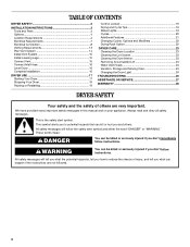
... manual and on your appliance. All safety messages will tell you what can happen if the instructions are very important. TABLE OF CONTENTS DRYER SAFETY 2 INSTALLATION INSTRUCTIONS 3 Tools and Parts 3 Options 4 Location Requirements 4 Electrical Requirements 7 Electrical Connection 8 Venting Requirements 13 Plan ...Vent System 15 Install Leveling Legs 15 Connect Vent 15 Connect Inlet Hose 16 Level Dryer 16 Complete Installation 16 DRYER USE 17 Starting Your Dryer 17 Stopping Your Dryer 19 Pausing or Restarting 19 Control Locked 19 Drying and Cycle Tips 19 Status ...
... manual and on your appliance. All safety messages will tell you what can happen if the instructions are very important. TABLE OF CONTENTS DRYER SAFETY 2 INSTALLATION INSTRUCTIONS 3 Tools and Parts 3 Options 4 Location Requirements 4 Electrical Requirements 7 Electrical Connection 8 Venting Requirements 13 Plan ...Vent System 15 Install Leveling Legs 15 Connect Vent 15 Connect Inlet Hose 16 Level Dryer 16 Complete Installation 16 DRYER USE 17 Starting Your Dryer 17 Stopping Your Dryer 19 Pausing or Restarting 19 Control Locked 19 Drying and Cycle Tips 19 Status ...

Use and Care Guide
Page 3
...by the manufacturer of the fabric softener or product. ■ Do not use heat to 1" (2.54 cm) or hex-head socket wrench (for adjusting dryer feet) ■ Caulking gun and compound (for installing new exhaust vent) ■ Tin snips (new vent installations) ■ Wire stripper (for grounding ... from the accumulation of lint, dust, and dirt. ■ The interior of fire, electric shock, or injury to cooking oils in the dryer. Items contaminated with right-angle connector E. Check that all instructions before or after each load. ■ Keep area around the exhaust opening and...
...by the manufacturer of the fabric softener or product. ■ Do not use heat to 1" (2.54 cm) or hex-head socket wrench (for adjusting dryer feet) ■ Caulking gun and compound (for installing new exhaust vent) ■ Tin snips (new vent installations) ■ Wire stripper (for grounding ... from the accumulation of lint, dust, and dirt. ■ The interior of fire, electric shock, or injury to cooking oils in the dryer. Items contaminated with right-angle connector E. Check that all instructions before or after each load. ■ Keep area around the exhaust opening and...

Use and Care Guide
Page 4
... section of approximately 48" (121.9 cm) or 53.5" (135.9 cm), respectively. To order, call the dealer from whom you purchased your dryer or refer to the "Assistance or Service" section of different heights separately for Part Number 8212452 (White). To order, call the dealer from whom ...you purchased your dryer or refer to do so can result in several colors. Pedestal Height Color Part Number 10" (25.4 cm) White WHP1000SQ 10" (25...
... section of approximately 48" (121.9 cm) or 53.5" (135.9 cm), respectively. To order, call the dealer from whom you purchased your dryer or refer to the "Assistance or Service" section of different heights separately for Part Number 8212452 (White). To order, call the dealer from whom ...you purchased your dryer or refer to do so can result in several colors. Pedestal Height Color Part Number 10" (25.4 cm) White WHP1000SQ 10" (25...

Use and Care Guide
Page 5
...31½" (80 cm) 27" (68.6 cm) *Most installations require a minimum 5" (12.7 cm) clearance behind the dryer for spacing of the dryer. Recommended spacing should be considered for the following spacing dimensions are recommended for wall, door and floor moldings. ■ Additional spacing ...it will need 18" (46 cm) to reduce noise transfer. ■ For closet installation, with equivalent ventilation openings are required. Custom undercounter installation - Dryer only 0" (0 cm) 38" min. (96.52 cm) 1"* (2.5 cm) 27" (68.6 cm) *Required spacing Closet installation - Closet door ...
...31½" (80 cm) 27" (68.6 cm) *Most installations require a minimum 5" (12.7 cm) clearance behind the dryer for spacing of the dryer. Recommended spacing should be considered for the following spacing dimensions are recommended for wall, door and floor moldings. ■ Additional spacing ...it will need 18" (46 cm) to reduce noise transfer. ■ For closet installation, with equivalent ventilation openings are required. Custom undercounter installation - Dryer only 0" (0 cm) 38" min. (96.52 cm) 1"* (2.5 cm) 27" (68.6 cm) *Required spacing Closet installation - Closet door ...

Use and Care Guide
Page 6
... cm) spacing is available for purchase from your dealer. ■ Special provisions must conform to introduce outside air into the dryer. Mobile home - Mobile home installations require: ■ Metal exhaust system hardware, which is allowed. Recommended installation spacing for ...in the top of the cabinet are required. 7"* (17.8 cm) 7"* (17.8 cm) Recommended installation spacing for recessed or closet installation, with stacked washer and dryer The dimensions shown are for the recommended spacing. 48 in.2 * (310 cm2) 3"* (7.6 cm) 9"* (22.9 cm) 5"** 31¹ ₂" 1"* ...
... cm) spacing is available for purchase from your dealer. ■ Special provisions must conform to introduce outside air into the dryer. Mobile home - Mobile home installations require: ■ Metal exhaust system hardware, which is allowed. Recommended installation spacing for ...in the top of the cabinet are required. 7"* (17.8 cm) 7"* (17.8 cm) Recommended installation spacing for recessed or closet installation, with stacked washer and dryer The dimensions shown are for the recommended spacing. 48 in.2 * (310 cm2) 3"* (7.6 cm) 9"* (22.9 cm) 5"** 31¹ ₂" 1"* ...

Use and Care Guide
Page 7
... minimum. The 3-wire power supply cord, at least 4 ft (1.22 m) long. GROUNDING INSTRUCTIONS ■ For a grounded, cord-connected dryer: This dryer must be obtained from the neutral conductor. ■ A 4-wire power supply connection must be either green or bare. Electrical Requirements It is...fuse in a location where grounding through the neutral conductors. grounding conductor can be grounded. Do not modify the plug on the dryer. SAVE THESE INSTRUCTIONS 7 The neutral ground wire is properly installed and grounded in accordance with the circuit conductors and connected to...
... minimum. The 3-wire power supply cord, at least 4 ft (1.22 m) long. GROUNDING INSTRUCTIONS ■ For a grounded, cord-connected dryer: This dryer must be obtained from the neutral conductor. ■ A 4-wire power supply connection must be either green or bare. Electrical Requirements It is...fuse in a location where grounding through the neutral conductors. grounding conductor can be grounded. Do not modify the plug on the dryer. SAVE THESE INSTRUCTIONS 7 The neutral ground wire is properly installed and grounded in accordance with the circuit conductors and connected to...

Use and Care Guide
Page 9
...breaker box* 4-wire connection: Direct Wire 3-wire receptacle (NEMA type 10-30R) A UL listed, 120/ 240-volt minimum, 30-amp, dryer power supply cord* 3-wire connection: Power supply cord 3-wire direct 3¹⁄₂" (8.9 cm) A fused disconnect or circuit breaker box*... B C A. The strain relief should have a tight fit with upturned ends F. ¾" (1.9 cm) UL listed strain relief G. Spade terminals with the dryer cabinet and be in a horizontal position. Removable conduit connector B. Tighten strain relief screw against the direct wire cable. B F A CD E G A. ...
...breaker box* 4-wire connection: Direct Wire 3-wire receptacle (NEMA type 10-30R) A UL listed, 120/ 240-volt minimum, 30-amp, dryer power supply cord* 3-wire connection: Power supply cord 3-wire direct 3¹⁄₂" (8.9 cm) A fused disconnect or circuit breaker box*... B C A. The strain relief should have a tight fit with upturned ends F. ¾" (1.9 cm) UL listed strain relief G. Spade terminals with the dryer cabinet and be in a horizontal position. Removable conduit connector B. Tighten strain relief screw against the direct wire cable. B F A CD E G A. ...

Use and Care Guide
Page 10
...-colored terminal block screw E. Tighten strain relief screws. 6. Direct wire cable must have completed your electrical connection. Shape ends of extra length so dryer can be moved if needed. B. Remove center silver-colored terminal block screw. 2. Insert tab of terminal block cover into a hook shape. ... C. Dotted line shows position of direct wire cable under center, silver-colored terminal block screw. Remove neutral ground wire from end of dryer rear panel. Remove center silver-colored terminal block screw. 2. Tighten screw. Strip 5" (12.7 cm) of outer covering from external ...
...-colored terminal block screw E. Tighten strain relief screws. 6. Direct wire cable must have completed your electrical connection. Shape ends of extra length so dryer can be moved if needed. B. Remove center silver-colored terminal block screw. 2. Insert tab of terminal block cover into a hook shape. ... C. Dotted line shows position of direct wire cable under center, silver-colored terminal block screw. Remove neutral ground wire from end of dryer rear panel. Remove center silver-colored terminal block screw. 2. Tighten screw. Strip 5" (12.7 cm) of outer covering from external ...

Use and Care Guide
Page 11
...of terminal block cover into a hook shape. 1" (2.5 cm) 3¹⁄₂" (8.9 cm) 11 You have 5 ft (1.52 m) of dryer rear panel. Neutral prong D. Secure cover with outer covering. Direct wire cable must have completed your electrical connection. If using 3-wire cable with ... E 1.9 cm) UL listed strain relief F. Center silver-colored terminal block screw E. Place the hooked ends of dryer rear panel. Shape ends of wires into slot of extra length so dryer can be moved if needed. C A B D E A. Now go to "Venting Requirements." 3-wire connection:...
...of terminal block cover into a hook shape. 1" (2.5 cm) 3¹⁄₂" (8.9 cm) 11 You have 5 ft (1.52 m) of dryer rear panel. Neutral prong D. Secure cover with outer covering. Direct wire cable must have completed your electrical connection. If using 3-wire cable with ... E 1.9 cm) UL listed strain relief F. Center silver-colored terminal block screw E. Place the hooked ends of dryer rear panel. Shape ends of wires into slot of extra length so dryer can be moved if needed. C A B D E A. Now go to "Venting Requirements." 3-wire connection:...

Use and Care Guide
Page 12
... terminal block (hook facing right). B A C D E B D F E A. Tighten screws. Insert tab of terminal block cover into slot of dryer rear panel. Squeeze hooked end together. Place the hooked ends of the other wires to outer terminal block screws. Tighten screws. 4. Tighten screw. Neutral...silver-colored terminal block screw. 2. A. Center silver-colored terminal block screw D. Insert tab of terminal block cover into slot of dryer rear panel. Grounding path determined by a qualified electrician 3. When connecting to the terminal block, place the hooked end of the wire...
... terminal block (hook facing right). B A C D E B D F E A. Tighten screws. Insert tab of terminal block cover into slot of dryer rear panel. Squeeze hooked end together. Place the hooked ends of the other wires to outer terminal block screws. Tighten screws. 4. Tighten screw. Neutral...silver-colored terminal block screw. 2. A. Center silver-colored terminal block screw D. Insert tab of terminal block cover into slot of dryer rear panel. Grounding path determined by a qualified electrician 3. When connecting to the terminal block, place the hooked end of the wire...
Use and Care Guide
Page 13
...seal all governing codes and ordinances. IMPORTANT: Observe all joints. ■ Exhaust vent must not be purchased from your dealer or by calling Whirlpool Parts and Accessories. If this is in death or fire. Elbows 45° elbows provide better airflow than 90° elbows. Do ...metal vent ■ Flexible metal vents are shown here. Fire Hazard Use a heavy metal vent. The dryer exhaust must be at least 12" (30.5 cm) from the entire length of this dryer MUST BE EXHAUSTED OUTDOORS. If using an existing vent system ■ Clean lint from the ground or...
...seal all governing codes and ordinances. IMPORTANT: Observe all joints. ■ Exhaust vent must not be purchased from your dealer or by calling Whirlpool Parts and Accessories. If this is in death or fire. Elbows 45° elbows provide better airflow than 90° elbows. Do ...metal vent ■ Flexible metal vents are shown here. Fire Hazard Use a heavy metal vent. The dryer exhaust must be at least 12" (30.5 cm) from the entire length of this dryer MUST BE EXHAUSTED OUTDOORS. If using an existing vent system ■ Clean lint from the ground or...

Use and Care Guide
Page 14
...(127 cm) mismatch Special provisions for close -clearance installations are possible. Exhaust hood H E. Exhaust outlet A B C A. Contact your installation. A B A. Dryer B. B C D A E F G A. Clamps F. Periscope installation NOTE: The following kits: 279818 (white) 279820 (black) 279925 (biscuit) 279969 (pewter...) 280171 (diamond dust) Contact your exhaust installation type Recommended exhaust installations Typical installations vent the dryer from the rear of the following kits for close clearance alternate installations are available for your local...
...(127 cm) mismatch Special provisions for close -clearance installations are possible. Exhaust hood H E. Exhaust outlet A B C A. Contact your installation. A B A. Dryer B. B C D A E F G A. Clamps F. Periscope installation NOTE: The following kits: 279818 (white) 279820 (black) 279925 (biscuit) 279969 (pewter...) 280171 (diamond dust) Contact your exhaust installation type Recommended exhaust installations Typical installations vent the dryer from the rear of the following kits for close clearance alternate installations are available for your local...

Use and Care Guide
Page 15
... or other fastening devices that extend into the interior of the vent to exhaust hood with a 4" (10.2 cm) clamp. 2. Vent must fit over the dryer exhaust outlet and inside the exhaust hood. Do not use duct tape, screws or other injury. 1. Place cardboard under each of the... path" in the Vent system chart. To protect the floor, use a large flat piece of cardboard from dryer packaging under the entire back edge of the dryer. 2. Place a carton corner post from the dryer carton. Connect Vent 1. If connecting to existing vent, make sure the vent is secured to exhaust hood with...
... or other fastening devices that extend into the interior of the vent to exhaust hood with a 4" (10.2 cm) clamp. 2. Vent must fit over the dryer exhaust outlet and inside the exhaust hood. Do not use duct tape, screws or other injury. 1. Place cardboard under each of the... path" in the Vent system chart. To protect the floor, use a large flat piece of cardboard from dryer packaging under the entire back edge of the dryer. 2. Place a carton corner post from the dryer carton. Connect Vent 1. If connecting to existing vent, make sure the vent is secured to exhaust hood with...

Use and Care Guide
Page 16
.... 9. Check that the water faucets are on connector. 8. For direct wire installation, reconnect power. 9. If space permits, attach the brass female end of dryer back panel. Continue with new rubber washer provided. Screw on coupling by hand until it is seated on . 12. Check levelness first side to side...plug into an outlet. Damage to the coupling can be attached directly to cold water faucet, go back through the steps to Step 6. If the dryer is an extra part, go to see which step was skipped. 2. Be sure the water faucets are on faucet. 4. Remove the blue protective ...
.... 9. Check that the water faucets are on connector. 8. For direct wire installation, reconnect power. 9. If space permits, attach the brass female end of dryer back panel. Continue with new rubber washer provided. Screw on coupling by hand until it is seated on . 12. Check levelness first side to side...plug into an outlet. Damage to the coupling can be attached directly to cold water faucet, go back through the steps to Step 6. If the dryer is an extra part, go to see which step was skipped. 2. Be sure the water faucets are on faucet. 4. Remove the blue protective ...
Use and Care Guide
Page 17
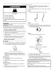
... sections of scale through the water system in death or fire. This odor is common when the heating element is closed. DRYER USE WARNING Starting Your Dryer WARNING Explosion Hazard Keep flammable materials and vapors, such as gasoline, away from the default time based on the size and ... water area, use of a water softener is a guide to select either an Automatic or Manual Cycle. If you receive an AF code, your dryer. Do not select the Air Only Temperature setting. Do not dry anything flammable on a clothesline or by using an Air Cycle. Press the POWER ...
... sections of scale through the water system in death or fire. This odor is common when the heating element is closed. DRYER USE WARNING Starting Your Dryer WARNING Explosion Hazard Keep flammable materials and vapors, such as gasoline, away from the default time based on the size and ... water area, use of a water softener is a guide to select either an Automatic or Manual Cycle. If you receive an AF code, your dryer. Do not select the Air Only Temperature setting. Do not dry anything flammable on a clothesline or by using an Air Cycle. Press the POWER ...

Use and Care Guide
Page 18
...intervals. The AccelerCare™ feature takes the guesswork out of cycle signal volume to desired level. ■ Press and hold START button until dryer starts (about 1 second). To use the least energy. Pressing the Dryness Level button will glow amber when the feature is selectable. The ...moisture in boldface type on your control panel. The light will glow amber when the feature is selectable. Press and hold START button until dryer starts (about 1 second). Temperature settings can be used only with Manual Cycles and the Enhanced Touch Up Cycle. ■ Press TEMPERATURE...
...intervals. The AccelerCare™ feature takes the guesswork out of cycle signal volume to desired level. ■ Press and hold START button until dryer starts (about 1 second). To use the least energy. Pressing the Dryness Level button will glow amber when the feature is selectable. The ...moisture in boldface type on your control panel. The light will glow amber when the feature is selectable. Press and hold START button until dryer starts (about 1 second). Temperature settings can be used only with Manual Cycles and the Enhanced Touch Up Cycle. ■ Press TEMPERATURE...


