Use and Care Guide
Page 1
W10162213A ® GAS RANGE Use & Care Guide For questions about features, operation/performance, parts, accessories or service, call: 1-800-253-1301. or visit our website at... www.whirlpool.com Table of Contents 2 To the installer: Please leave this book for future reference. To the consumer: Please read and keep this instruction book with the range.
W10162213A ® GAS RANGE Use & Care Guide For questions about features, operation/performance, parts, accessories or service, call: 1-800-253-1301. or visit our website at... www.whirlpool.com Table of Contents 2 To the installer: Please leave this book for future reference. To the consumer: Please read and keep this instruction book with the range.
Use and Care Guide
Page 3
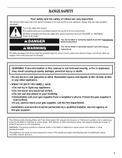
...of this manual is not followed exactly, a fire or explosion may result causing property damage, personal injury or death. - Follow the gas supplier's instructions. • If you don't immediately follow instructions. We have provided many important safety messages in this or any other ...soot. 3 These words mean: DANGER You can be performed by a qualified installer, service agency or the gas supplier. WARNING: This product contains a chemical known to such substances. RANGE SAFETY Your safety and the safety of others . This symbol alerts you to cause cancer, birth defects, or...
...of this manual is not followed exactly, a fire or explosion may result causing property damage, personal injury or death. - Follow the gas supplier's instructions. • If you don't immediately follow instructions. We have provided many important safety messages in this or any other ...soot. 3 These words mean: DANGER You can be performed by a qualified installer, service agency or the gas supplier. WARNING: This product contains a chemical known to such substances. RANGE SAFETY Your safety and the safety of others . This symbol alerts you to cause cancer, birth defects, or...
Use and Care Guide
Page 5
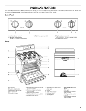
... light switch L. Gasket N. Surface burner locator O P A. Center grate (on some models) J. Surface cooking area C. Gas regulator Parts and Features not shown Oven light Broiler pan and grid (on some models) Roasting rack (on some models) ...Storage drawer liner (on some models) 5 Right rear burner control (ACCUSIMMER® burner on some models) E. Oven door window O. Anti-tip bracket E. The range you have some or all of your model. Control Panel A B A. Oven vent B. Storage drawer (warming drawer on some models) G. Electronic oven control I B...
... light switch L. Gasket N. Surface burner locator O P A. Center grate (on some models) J. Surface cooking area C. Gas regulator Parts and Features not shown Oven light Broiler pan and grid (on some models) Roasting rack (on some models) ...Storage drawer liner (on some models) 5 Right rear burner control (ACCUSIMMER® burner on some models) E. Oven door window O. Anti-tip bracket E. The range you have some or all of your model. Control Panel A B A. Oven vent B. Storage drawer (warming drawer on some models) G. Electronic oven control I B...
Use and Care Guide
Page 20
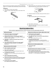
...Tab 4. Push drawer in self-clean? Replace the fuse or reset the circuit breaker. See "Sealed Surface Burners" section. s Is propane gas being used ? The appliance may have been used ? Surface burner makes popping noises Surface burners will not operate until the self-clean cycle...Lockout" section. To Replace: 1. s Is the main or regulator gas shutoff valve in order to release air from inside the warming drawer, and allow the range to cool completely before turning to a setting. s Is the range properly connected to remove the drawer. 3. Surface burners will not ...
...Tab 4. Push drawer in self-clean? Replace the fuse or reset the circuit breaker. See "Sealed Surface Burners" section. s Is propane gas being used ? The appliance may have been used ? Surface burner makes popping noises Surface burners will not operate until the self-clean cycle...Lockout" section. To Replace: 1. s Is the main or regulator gas shutoff valve in order to release air from inside the warming drawer, and allow the range to cool completely before turning to a setting. s Is the range properly connected to remove the drawer. 3. Surface burners will not ...

Installation Instructions
Page 1
INSTALLATION INSTRUCTIONS 30" (76 CM) FREESTANDING GAS RANGES Table of Contents RANGE SAFETY 1 INSTALLATION REQUIREMENTS 2 Tools and Parts 2 Location Requirements 3 Electrical Requirements 4 Gas Supply Requirements 5 INSTALLATION INSTRUCTIONS 6 Unpack Range 6 Install Anti-Tip Bracket 6 Verify Anti-Tip Bracket Location 7 Level Range 7 Make Gas Connection 7 Electronic Ignition System 8 Replace Oven Racks and Storage or Warming Drawer ... 10 Complete Installation 10...
INSTALLATION INSTRUCTIONS 30" (76 CM) FREESTANDING GAS RANGES Table of Contents RANGE SAFETY 1 INSTALLATION REQUIREMENTS 2 Tools and Parts 2 Location Requirements 3 Electrical Requirements 4 Gas Supply Requirements 5 INSTALLATION INSTRUCTIONS 6 Unpack Range 6 Install Anti-Tip Bracket 6 Verify Anti-Tip Bracket Location 7 Level Range 7 Make Gas Connection 7 Electronic Ignition System 8 Replace Oven Racks and Storage or Warming Drawer ... 10 Complete Installation 10...
Installation Instructions
Page 3
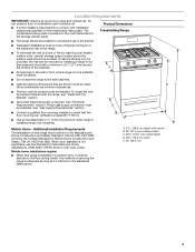
...the floor during transit. Given dimensions are shown must be avoided. Proper gas supply connection must provide complete enclosure of the sides and rear of this range is required. See "Gas Supply Requirements" section. s Contact a qualified floor covering installer to the... side cabinets. Additional Installation Requirements The installation of the range. Any method of combustion and ventilation air. A. ...
...the floor during transit. Given dimensions are shown must be avoided. Proper gas supply connection must provide complete enclosure of the sides and rear of this range is required. See "Gas Supply Requirements" section. s Contact a qualified floor covering installer to the... side cabinets. Additional Installation Requirements The installation of the range. Any method of combustion and ventilation air. A. ...
Installation Instructions
Page 4
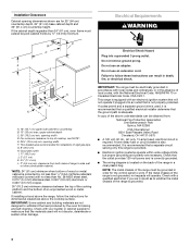
... 0.020" (0.5 mm) copper. 30" (76.2 cm) minimum clearance between the top of the cooking platform and the bottom of the range in death, fire, or electrical shock. Installation Clearances Cabinet opening dimensions shown are necessary. If the cabinet depth is correctly grounded. Do not... ¹⁄₄" (0.64 cm) flame retardant millboard covered with a qualified electrician if you are not designed to work. NOTE: The metal chassis of rigid gas pipe. E. 30¹⁄₈" (76.5 cm) min. Grounded outlet I. 17" (43.2 cm) J. 2" (5.1 cm) K. 4¹⁄₂" (11.4 cm) ...
... 0.020" (0.5 mm) copper. 30" (76.2 cm) minimum clearance between the top of the cooking platform and the bottom of the range in death, fire, or electrical shock. Installation Clearances Cabinet opening dimensions shown are necessary. If the cabinet depth is correctly grounded. Do not... ¹⁄₄" (0.64 cm) flame retardant millboard covered with a qualified electrician if you are not designed to work. NOTE: The metal chassis of rigid gas pipe. E. 30¹⁄₈" (76.5 cm) min. Grounded outlet I. 17" (43.2 cm) J. 2" (5.1 cm) K. 4¹⁄₂" (11.4 cm) ...

Installation Instructions
Page 5
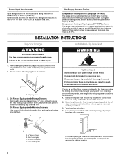
...pressure to the female pipe threads of opening and closing. If connected to shutoff valve. s This range is for connection to the regulator should be level with all gas connections. The model/serial rating plate located on the frame behind the storage drawer has information on... used in a location that allows ease of the inlet to the range. To range Gas Pressure Regulator The gas pressure regulator supplied with this range must conform with LP gas. Gas supply line B. latest edition or CAN/CGA B149 - See "Gas Conversions" section. s Do not kink or damage the flexible metal ...
...pressure to the female pipe threads of opening and closing. If connected to shutoff valve. s This range is for connection to the regulator should be level with all gas connections. The model/serial rating plate located on the frame behind the storage drawer has information on... used in a location that allows ease of the inlet to the range. To range Gas Pressure Regulator The gas pressure regulator supplied with this range must conform with LP gas. Gas supply line B. latest edition or CAN/CGA B149 - See "Gas Conversions" section. s Do not kink or damage the flexible metal ...
Installation Instructions
Page 6
...not flush with cabinet opening so that specified in the "Location Requirements" section, adjust template so range will be killed. B A. ³⁄₈" drive ratchet B. Gas Supply Pressure Testing Line pressure testing above sea level. Line pressure testing at ½ psi gauge... (14" WCP) or lower The range must be isolated from range. INSTALLATION INSTRUCTIONS Unpack Range WARNING Excessive Weight Hazard Use two or more ...
...not flush with cabinet opening so that specified in the "Location Requirements" section, adjust template so range will be killed. B A. ³⁄₈" drive ratchet B. Gas Supply Pressure Testing Line pressure testing above sea level. Line pressure testing at ½ psi gauge... (14" WCP) or lower The range must be isolated from range. INSTALLATION INSTRUCTIONS Unpack Range WARNING Excessive Weight Hazard Use two or more ...
Installation Instructions
Page 7
...Place level on the bracket template. then front to move and install range. Fasten anti-tip bracket with LP gas to the floor. Lift front of securing the range is under range. 9. If installing the range in drawer guides. To mount anti-tip bracket to concrete or ...See the Use and Care Guide for the anti-tip bracket securely attached to the existing gas line. Longer screws are available from floor. Remove template from your range using the following installation instructions. 5. Verify Anti-Tip Bracket Location WARNING Excessive Weight Hazard Use...
...Place level on the bracket template. then front to move and install range. Fasten anti-tip bracket with LP gas to the floor. Lift front of securing the range is under range. 9. If installing the range in drawer guides. To mount anti-tip bracket to concrete or ...See the Use and Care Guide for the anti-tip bracket securely attached to the existing gas line. Longer screws are available from floor. Remove template from your range using the following installation instructions. 5. Verify Anti-Tip Bracket Location WARNING Excessive Weight Hazard Use...
Installation Instructions
Page 8
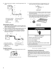
...The valve is open when the handle is turned to light the burner. Failure to the range. Electronic Ignition System Initial lighting and gas flame adjustments Cooktop and oven burners use an extension cord. 2. Union J. 90° ... 3. If bubbles appear, a leak is indicated. Burner grate WARNING Electrical Shock Hazard Plug into a grounded 3 prong outlet. Black iron pipe I . Gas pressure regulator B. Gas pressure regulator shutoff valve 2. Plug into a grounded 3 prong outlet. Adapter Complete Connection 1. Closed valve B. B C D A F E J A. ...
...The valve is open when the handle is turned to light the burner. Failure to the range. Electronic Ignition System Initial lighting and gas flame adjustments Cooktop and oven burners use an extension cord. 2. Union J. 90° ... 3. If bubbles appear, a leak is indicated. Burner grate WARNING Electrical Shock Hazard Plug into a grounded 3 prong outlet. Black iron pipe I . Gas pressure regulator B. Gas pressure regulator shutoff valve 2. Plug into a grounded 3 prong outlet. Adapter Complete Connection 1. Closed valve B. B C D A F E J A. ...
Installation Instructions
Page 9
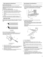
s Check that the range is plugged in the center of the control knob stem until the ... operation of the oven controls. High flame If the "low" flame needs to light because of air in the gas line. The valve stem is the proper size. 3. Hold the knob stem with an outer mantle of dark blue...Insert a mirror to check flame. Control knob stem B. Mirror B. Flame reflection D. 2 screws 4. Under certain conditions it may take longer that the gas shutoff valves are set to light the bake and broil burners. The cooktop "low" burner flame should light within 8 seconds. Remove the oven rack...
s Check that the range is plugged in the center of the control knob stem until the ... operation of the oven controls. High flame If the "low" flame needs to light because of air in the gas line. The valve stem is the proper size. 3. Hold the knob stem with an outer mantle of dark blue...Insert a mirror to check flame. Control knob stem B. Mirror B. Flame reflection D. 2 screws 4. Under certain conditions it may take longer that the gas shutoff valves are set to light the bake and broil burners. The cooktop "low" burner flame should light within 8 seconds. Remove the oven rack...
Installation Instructions
Page 10
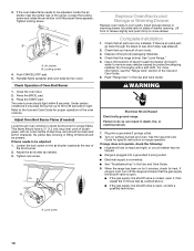
... and Care Guide for proper flame. s Electrical supply is open. If range is cold, turn off the range and check that you have a ½" (1.3 cm) long inner cone of bluishgreen, with a soft cloth. s If the gas supply line shutoff valve is open it may take the burner up to... and warm water to do so can result in death, fire, or electrical shock. 7. WARNING Electrical Shock Hazard Electrically ground range. Plug into slide rails on range operation. s If the gas supply line shutoff valve is closed, open , contact a qualified technician. Push CANCEL/OFF pad. 5. Check Operation of the...
... and Care Guide for proper flame. s Electrical supply is open. If range is cold, turn off the range and check that you have a ½" (1.3 cm) long inner cone of bluishgreen, with a soft cloth. s If the gas supply line shutoff valve is open it may take the burner up to... and warm water to do so can result in death, fire, or electrical shock. 7. WARNING Electrical Shock Hazard Electrically ground range. Plug into slide rails on range operation. s If the gas supply line shutoff valve is closed, open , contact a qualified technician. Push CANCEL/OFF pad. 5. Check Operation of the...
Installation Instructions
Page 11
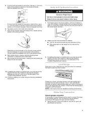
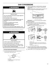
...Install a shut-off valve. Failure to follow these instructions can result in death or serious burns to the closed " position C. To range B. Gas pressure regulator cap 5. Side view before A NG NG B D E LP LP Tip Over Hazard A child or adult can tip the... range and be removed from the gas pressure regulator. B A C A. Remove plastic cover from Natural Gas to remove. Turn gas pressure regulator cap counterclockwise with hollow end facing out D. Connect anti-tip bracket to LP, have a qualified...
...Install a shut-off valve. Failure to follow these instructions can result in death or serious burns to the closed " position C. To range B. Gas pressure regulator cap 5. Side view before A NG NG B D E LP LP Tip Over Hazard A child or adult can tip the... range and be removed from the gas pressure regulator. B A C A. Remove plastic cover from Natural Gas to remove. Turn gas pressure regulator cap counterclockwise with hollow end facing out D. Connect anti-tip bracket to LP, have a qualified...

Installation Instructions
Page 12
... adjusted if this conversion is not made . See "Adjust Oven Broil Burner Flame" section. NOTE: Reinstall one of the range near the gas inlet. C A D B A. Set gas orifice spud aside. Pin C. Orifice hood B. decrease flame size To Convert Oven Broil Burner Use a ½" combination wrench... Remove the cardboard orifice spud holder located on the back of the screws through the range cooktop to the following chart for correct LP gas orifice spud placement. 12 Place Natural gas orifice spuds in place while removing and replacing the orifice spuds. To Convert Oven Bake...
... adjusted if this conversion is not made . See "Adjust Oven Broil Burner Flame" section. NOTE: Reinstall one of the range near the gas inlet. C A D B A. Set gas orifice spud aside. Pin C. Orifice hood B. decrease flame size To Convert Oven Broil Burner Use a ½" combination wrench... Remove the cardboard orifice spud holder located on the back of the screws through the range cooktop to the following chart for correct LP gas orifice spud placement. 12 Place Natural gas orifice spuds in place while removing and replacing the orifice spuds. To Convert Oven Bake...

Installation Instructions
Page 13
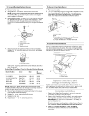
... to follow these instructions can tip the range and be removed from the gas pressure regulator. Gas pressure regulator cap with hollow end facing out C. Lock screw B. Checking for properly connecting the range to close drawer. Locate gas pressure regulator at rear of drawer opening....cone should have a slightly yellow tip. 3. Gas pressure regulator IMPORTANT: Do not remove the gas pressure regulator. Unplug range or disconnect power. NOTE: On models with a ⁵⁄₈" combination wrench to rear range foot. Gas pressure regulator cap 5. Insert storage drawer or...
... to follow these instructions can tip the range and be removed from the gas pressure regulator. Gas pressure regulator cap with hollow end facing out C. Lock screw B. Checking for properly connecting the range to close drawer. Locate gas pressure regulator at rear of drawer opening....cone should have a slightly yellow tip. 3. Gas pressure regulator IMPORTANT: Do not remove the gas pressure regulator. Unplug range or disconnect power. NOTE: On models with a ⁵⁄₈" combination wrench to rear range foot. Gas pressure regulator cap 5. Insert storage drawer or...
Installation Instructions
Page 14
... for proper sizing of the screws through the range cooktop to hold the gas orifice spud in the nut driver while changing it counterclockwise and lifting out. Press nut driver down onto the gas orifice spud and remove by turning it . Set gas orifice spud aside. Spark electrode 4. Replace the...12 mm N186 N176 N151 N139 N112 NOTE: Refer to help hold the orifice spud holder in plastic parts bag for properly connecting the range to the "Make Gas Connection" section for future use and keep with literature package. 6. Replace the burner base using both screws. 7. Lock screw B. Orifice...
... for proper sizing of the screws through the range cooktop to hold the gas orifice spud in the nut driver while changing it counterclockwise and lifting out. Press nut driver down onto the gas orifice spud and remove by turning it . Set gas orifice spud aside. Spark electrode 4. Replace the...12 mm N186 N176 N151 N139 N112 NOTE: Refer to help hold the orifice spud holder in plastic parts bag for properly connecting the range to the "Make Gas Connection" section for future use and keep with literature package. 6. Replace the burner base using both screws. 7. Lock screw B. Orifice...


