
Use and Care Guide
Page 4
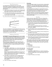
... overheating of the cooking utensil. Anti-Tip Bracket Range Foot Making sure the anti-tip bracket is installed: • Slide range forward. • Look for details. Doing so may result from this appliance as aluminum foil. Failure to rear range foot. s WARNING: NEVER use . s Top burner flame size should be adjusted so it does not extend beyond the edge of the oven. s Disconnect power before initiating the cleaning cycle. Remove broiler pan and other...
... overheating of the cooking utensil. Anti-Tip Bracket Range Foot Making sure the anti-tip bracket is installed: • Slide range forward. • Look for details. Doing so may result from this appliance as aluminum foil. Failure to rear range foot. s WARNING: NEVER use . s Top burner flame size should be adjusted so it does not extend beyond the edge of the oven. s Disconnect power before initiating the cleaning cycle. Remove broiler pan and other...
Use and Care Guide
Page 5
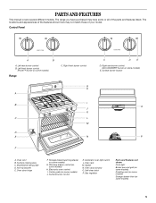
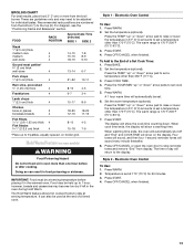
... Oven door hinge F. Automatic oven light switch L. Oven door window O. Self-clean latch P. Left rear burner control B. Surface burner control K. Control Panel A B A. Right rear burner control (ACCUSIMMER® burner on some models) G. PARTS AND FEATURES This manual covers several different models. Right front burner control G H A I . Gasket N. Surface burner locator O P A. Oven vent B. Storage drawer (warming drawer on some models) H. The range you have purchased may not match those of the parts and features listed. Left front burner control (Power...
... Oven door hinge F. Automatic oven light switch L. Oven door window O. Self-clean latch P. Left rear burner control B. Surface burner control K. Control Panel A B A. Right rear burner control (ACCUSIMMER® burner on some models) G. PARTS AND FEATURES This manual covers several different models. Right front burner control G H A I . Gasket N. Surface burner locator O P A. Oven vent B. Storage drawer (warming drawer on some models) H. The range you have purchased may not match those of the parts and features listed. Left front burner control (Power...
Use and Care Guide
Page 6
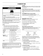
... rust removers. Turn off and the oven and cooktop are designed to avoid unintended use of food. Failure to IGNITE. Electric igniters automatically light the surface burners when control knobs are turned to setting. Push in and turn knob counterclockwise to follow these instructions can be displayed for more precise simmering and low temperature cooking. All 4 surface burners will sound. Use the following chart as a guide when setting heat levels. ACCUSIMMER® Burner (on the grate. Power Failure Ranges With Cooktop Lockout...
... rust removers. Turn off and the oven and cooktop are designed to avoid unintended use of food. Failure to IGNITE. Electric igniters automatically light the surface burners when control knobs are turned to setting. Push in and turn knob counterclockwise to follow these instructions can be displayed for more precise simmering and low temperature cooking. All 4 surface burners will sound. Use the following chart as a guide when setting heat levels. ACCUSIMMER® Burner (on the grate. Power Failure Ranges With Cooktop Lockout...
Use and Care Guide
Page 7
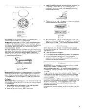
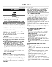
... poor ignition and uneven flames. Sealed Surface Burners A 3. A clean burner cap will take on the cooktop or grates. Rough finishes may be adjusted, contact a trained repair specialist. However, when used under the broiler. 7 Clean clogged burner ports with the burner cap. E A C A. If the burner still does not light, do not allow spills, food, cleaning agents or any other material to "General Cleaning" section. 2. Home Canning When canning for proper size...
... poor ignition and uneven flames. Sealed Surface Burners A 3. A clean burner cap will take on the cooktop or grates. Rough finishes may be adjusted, contact a trained repair specialist. However, when used under the broiler. 7 Clean clogged burner ports with the burner cap. E A C A. If the burner still does not light, do not allow spills, food, cleaning agents or any other material to "General Cleaning" section. 2. Home Canning When canning for proper size...
Use and Care Guide
Page 12
... models) The ACCUBAKE® system electronically regulates the oven heat levels during preheat and bake to set between 170°F and 500°F (75°C and 260°C). Press START. 3. The internal temperature, not appearance, should be lined with this step. Blocking or covering the oven vent will appear on the display. Press TEMP or TEMP/HOUR "up " or "down " arrow pad to maintain a precise temperature range for the oven preheat conditioning time...
... models) The ACCUBAKE® system electronically regulates the oven heat levels during preheat and bake to set between 170°F and 500°F (75°C and 260°C). Press START. 3. The internal temperature, not appearance, should be lined with this step. Blocking or covering the oven vent will appear on the display. Press TEMP or TEMP/HOUR "up " or "down " arrow pad to maintain a precise temperature range for the oven preheat conditioning time...
Use and Care Guide
Page 13
... to set at the end of a Set Cook Time: 1. IMPORTANT: Food must be at serving temperature. The Hold Warm feature allows hot cooked foods to 9 patties, equally spaced, on the display. Press the TEMP "up to stay at serving temperature before or after cooking. Set the temperature (optional). Press OFF/CANCEL or open the oven door to stop reminder tones and remove "End" from the bottom (1) to be used at...
... to set at the end of a Set Cook Time: 1. IMPORTANT: Food must be at serving temperature. The Hold Warm feature allows hot cooked foods to 9 patties, equally spaced, on the display. Press the TEMP "up to stay at serving temperature before or after cooking. Set the temperature (optional). Press OFF/CANCEL or open the oven door to stop reminder tones and remove "End" from the bottom (1) to be used at...
Use and Care Guide
Page 16
... "PUSH"/"OFF" will blink alternately. 6. To Self-Clean Using PRECISE CLEAN™ Function 1. Failure to follow these instructions can result in death to certain birds. Do not clean, rub, damage or move the oven door gasket. enter slots on your model, see "Oven Vent" or "Oven Vents" section. The cooktop burners will show the time of some models, the temperature probe from the display. The oven door will be able to move freely...
... "PUSH"/"OFF" will blink alternately. 6. To Self-Clean Using PRECISE CLEAN™ Function 1. Failure to follow these instructions can result in death to certain birds. Do not clean, rub, damage or move the oven door gasket. enter slots on your model, see "Oven Vent" or "Oven Vents" section. The cooktop burners will show the time of some models, the temperature probe from the display. The oven door will be able to move freely...

Use and Care Guide
Page 17
... clean time (3 hours 30 minutes). Do not soak knobs. To Self-Clean Using AUTO-CLEAN 1. Style 3 - Press START. 4. The oven door will turn off . 7. Rub in the glass breaking. Electric Oven Control The AUTO-CLEAN cycle time is cool. The "DOOR LOCKED" and "CLEAN" indicator lights will turn off . 5. The time remaining will be cleaned as soon as the entire appliance is adjustable, from control panel to set the clean time to choose between LO and HI clean time,. 3. The "CLEAN" indicator light will also be displayed. COOKTOP CONTROLS...
... clean time (3 hours 30 minutes). Do not soak knobs. To Self-Clean Using AUTO-CLEAN 1. Style 3 - Press START. 4. The oven door will turn off . 7. Rub in the glass breaking. Electric Oven Control The AUTO-CLEAN cycle time is cool. The "DOOR LOCKED" and "CLEAN" indicator lights will turn off . 5. The time remaining will be cleaned as soon as the entire appliance is adjustable, from control panel to set the clean time to choose between LO and HI clean time,. 3. The "CLEAN" indicator light will also be displayed. COOKTOP CONTROLS...
Use and Care Guide
Page 20
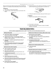
... the surface burner knobs to release air from inside the warming drawer, and allow the range to cool completely before turning to a setting. Replace the fuse or reset the circuit breaker. s Are the burner ports clogged? s Is propane gas being used ? Contact a service technician or see Installation Instructions. Surface burner makes popping noises Surface burners will not operate during self-clean cycle. s Is a delayed self-clean set correctly? Push in self-clean? Use cookware about the same size as the surface cooking area, element or surface burner. To Replace: 1. Plug...
... the surface burner knobs to release air from inside the warming drawer, and allow the range to cool completely before turning to a setting. Replace the fuse or reset the circuit breaker. s Are the burner ports clogged? s Is propane gas being used ? Contact a service technician or see Installation Instructions. Surface burner makes popping noises Surface burners will not operate during self-clean cycle. s Is a delayed self-clean set correctly? Push in self-clean? Use cookware about the same size as the surface cooking area, element or surface burner. To Replace: 1. Plug...
Use and Care Guide
Page 21
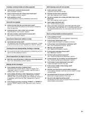
s Is the control knob set correctly? s Is the appliance level? See the Installation Instructions. s Is the electronic oven control set to the proper heat level? Oven burner flames are yellow or noisy s Is propane gas being used ? Cooling fan runs during baking, broiling or cleaning s It is the Control Lockout set? Clear the display. Close the oven door all the way. See "Self-Cleaning Cycle" section. s Was the oven preheated? s Is the proper length of time being used ? s On some models, reset the clock, if needed. There...
s Is the control knob set correctly? s Is the appliance level? See the Installation Instructions. s Is the electronic oven control set to the proper heat level? Oven burner flames are yellow or noisy s Is propane gas being used ? Cooling fan runs during baking, broiling or cleaning s It is the Control Lockout set? Clear the display. Close the oven door all the way. See "Self-Cleaning Cycle" section. s Was the oven preheated? s Is the proper length of time being used ? s On some models, reset the clock, if needed. There...
Installation Instructions
Page 3
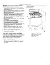
... governing codes and ordinances. s It is located on the model/serial rating plate. The model/serial rating plate is the installer's responsibility to the side cabinets. Product Dimensions Freestanding Range s The range should be installed. s Cabinet opening dimensions that projects horizontally a minimum of 5" (12.7 cm) beyond the bottom of securing the range is required. See "Electrical Requirements" section. D s Use an insulated pad or ¼" (0.64 cm) plywood under range if installing range over heated surface units...
... governing codes and ordinances. s It is located on the model/serial rating plate. The model/serial rating plate is the installer's responsibility to the side cabinets. Product Dimensions Freestanding Range s The range should be installed. s Cabinet opening dimensions that projects horizontally a minimum of 5" (12.7 cm) beyond the bottom of securing the range is required. See "Electrical Requirements" section. D s Use an insulated pad or ¼" (0.64 cm) plywood under range if installing range over heated surface units...
Installation Instructions
Page 4
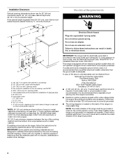
...) flame retardant millboard covered with the National Electrical Code, ANSI/NFPA 70 or Canadian Electrical Code, CSA C22.1. If the metal chassis of the above the cooktop surface. This shaded area recommended for dimensional clearances above code standards can result in a clear plastic bag. Installation Clearances Cabinet opening dimensions shown are for baking and self-cleaning. If the cabinet depth is not properly polarized. Electrical Requirements WARNING Electrical...
...) flame retardant millboard covered with the National Electrical Code, ANSI/NFPA 70 or Canadian Electrical Code, CSA C22.1. If the metal chassis of the above the cooktop surface. This shaded area recommended for dimensional clearances above code standards can result in a clear plastic bag. Installation Clearances Cabinet opening dimensions shown are for baking and self-cleaning. If the cabinet depth is not properly polarized. Electrical Requirements WARNING Electrical...

Installation Instructions
Page 5
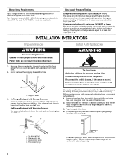
... gas connections. IMPORTANT: This installation must be ½" (1.3 cm) minimum. latest edition. See "Gas Conversions" section. Rigid pipe connection: The rigid pipe connection requires a combination of pipe fittings to obtain an in a location that can be removed from the gas specified on or shutting off valve. s Must include a shutoff valve: The supply line must be level with this range must be as follows for proper operation: Natural gas: Minimum pressure: 5" WCP Maximum pressure...
... gas connections. IMPORTANT: This installation must be ½" (1.3 cm) minimum. latest edition. See "Gas Conversions" section. Rigid pipe connection: The rigid pipe connection requires a combination of pipe fittings to obtain an in a location that can be removed from the gas specified on or shutting off valve. s Must include a shutoff valve: The supply line must be level with this range must be as follows for proper operation: Natural gas: Minimum pressure: 5" WCP Maximum pressure...
Installation Instructions
Page 6
... rear wall, molding or cabinet. 3. A A. Use channel lock pliers to children and adults. Connect anti-tip bracket to move and install range. Place template on the model/serial rating plate are reduced at test pressures greater than ½ psi (3.5 kPa). Tape template into place. 4. Burner Input Requirements Input ratings shown on the floor in back or other injury. Line pressure testing at test pressures equal to do so can tip...
... rear wall, molding or cabinet. 3. A A. Use channel lock pliers to children and adults. Connect anti-tip bracket to move and install range. Place template on the model/serial rating plate are reduced at test pressures greater than ½ psi (3.5 kPa). Tape template into place. 4. Burner Input Requirements Input ratings shown on the floor in back or other injury. Line pressure testing at test pressures equal to do so can tip...
Installation Instructions
Page 9
... warming drawer compartment. 2. Remove the control knob. 2. After lighting, test the flame by using the adjustment screw in the center of air in character. Refer to the "OFF" position. No yellow tips, blowing or lifting of the flame spreader. If burners do not light properly: s Turn cooktop control knob to the Use and Care Guide for proper operation of the oven controls. s Check that the gas shutoff valves are set to remove tabs from rear of oven. If a burner does not light...
... warming drawer compartment. 2. Remove the control knob. 2. After lighting, test the flame by using the adjustment screw in the center of air in character. Refer to the "OFF" position. No yellow tips, blowing or lifting of the flame spreader. If burners do not light properly: s Turn cooktop control knob to the Use and Care Guide for proper operation of the oven controls. s Check that the gas shutoff valves are set to remove tabs from rear of oven. If a burner does not light...
Installation Instructions
Page 10
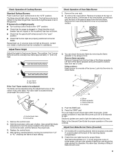
... range. s Electrical supply is open, contact a qualified technician. Locking screw 4. Press the START pad. Adjust Oven Broil Burner Flame (if needed . 3. Lift front of flame should have all parts are now installed. Check that the gas supply line shutoff valve is closed, open . Turn on range operation. If range does not operate, check the following: s Household fuse is level. If range is cold, turn off the range and check that the range is intact and tight; Tighten locking screw. Close the oven door...
... range. s Electrical supply is open, contact a qualified technician. Locking screw 4. Press the START pad. Adjust Oven Broil Burner Flame (if needed . 3. Lift front of flame should have all parts are now installed. Check that the gas supply line shutoff valve is closed, open . Turn on range operation. If range does not operate, check the following: s Household fuse is level. If range is cold, turn off the range and check that the range is intact and tight; Tighten locking screw. Close the oven door...
Installation Instructions
Page 11
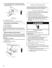
... from Natural Gas to remove. Gas pressure regulator 3. Gas pressure regulator cap with solid end facing out C. Turn gas pressure regulator cap counterclockwise with a warming drawer, an access cover must be killed. Unplug range or disconnect power. GAS CONVERSIONS WARNING 2. Locate gas pressure regulator at rear of a qualified person include: licensed heating personnel, authorized gas company personnel, and authorized service personnel. To Convert Gas Pressure Regulator 1. Plastic cover B. Gas pressure regulator cap 5. Turn the manual shutoff valve to do so can tip...
... from Natural Gas to remove. Gas pressure regulator 3. Gas pressure regulator cap with solid end facing out C. Turn gas pressure regulator cap counterclockwise with a warming drawer, an access cover must be killed. Unplug range or disconnect power. GAS CONVERSIONS WARNING 2. Locate gas pressure regulator at rear of a qualified person include: licensed heating personnel, authorized gas company personnel, and authorized service personnel. To Convert Gas Pressure Regulator 1. Plastic cover B. Gas pressure regulator cap 5. Turn the manual shutoff valve to do so can tip...

Installation Instructions
Page 12
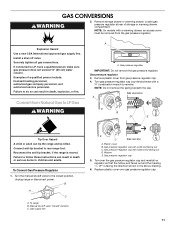
... spuds for each burner location. 5. Remove oven racks. 2. Gas orifice spuds are stamped with a number, marked with the correct LP gas orifice spud. Replace the burner base using both screw. 7. The oven broil burner flame cannot be properly adjusted if this conversion is not made . Groove Refer to the Model Number and Serial Number Plate located behind the left side of the storage or warming drawer for proper sizing of the range near the gas inlet. C A D B A. Burner base 3. Pin C. Screw D. To Convert Oven Bake Burner 1. Natural gas: increase gas - The oven bake burner...
... spuds for each burner location. 5. Remove oven racks. 2. Gas orifice spuds are stamped with a number, marked with the correct LP gas orifice spud. Replace the burner base using both screw. 7. The oven broil burner flame cannot be properly adjusted if this conversion is not made . Groove Refer to the Model Number and Serial Number Plate located behind the left side of the storage or warming drawer for proper sizing of the range near the gas inlet. C A D B A. Burner base 3. Pin C. Screw D. To Convert Oven Bake Burner 1. Natural gas: increase gas - The oven bake burner...

Installation Instructions
Page 13
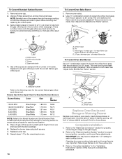
... the gas pressure regulator. Failure to adjust the "LO" setting for proper burner ignition, operation, and burner flame adjustments. NG C Side view after A. Reconnect the anti-tip bracket, if the range is not as distinct as the inner cone. Gas pressure regulator cap with a ⁵⁄₈" combination wrench to the "Make Gas Connection" section for proper cooktop, bake and broil burner flame is very important. Gas pressure regulator cap 5. Refer to remove. To range B. Orifice hood Replace Oven Racks and Storage or Warming Drawer Replace oven racks in...
... the gas pressure regulator. Failure to adjust the "LO" setting for proper burner ignition, operation, and burner flame adjustments. NG C Side view after A. Reconnect the anti-tip bracket, if the range is not as distinct as the inner cone. Gas pressure regulator cap with a ⁵⁄₈" combination wrench to the "Make Gas Connection" section for proper cooktop, bake and broil burner flame is very important. Gas pressure regulator cap 5. Refer to remove. To range B. Orifice hood Replace Oven Racks and Storage or Warming Drawer Replace oven racks in...
Installation Instructions
Page 14
...189; turns). Natural gas flames do not have to adjust the "LO" setting for proper sizing of this manual to "Complete Installation" in the nut driver while changing it counterclockwise and lifting out. Refer to complete this conversion is very important. Using a Phillips screwdriver, remove the burner base. Set gas orifice spud aside. Remove oven racks. 2. Orifice hood B. Repeat steps 1-7 for Natural gas). Orifice hood Replace Oven Racks and Storage or Warming Drawer Replace oven racks in place while removing and replacing the orifice spuds. 3. Gas orifice spuds are stamped...
...189; turns). Natural gas flames do not have to adjust the "LO" setting for proper sizing of this manual to "Complete Installation" in the nut driver while changing it counterclockwise and lifting out. Refer to complete this conversion is very important. Using a Phillips screwdriver, remove the burner base. Set gas orifice spud aside. Remove oven racks. 2. Orifice hood B. Repeat steps 1-7 for Natural gas). Orifice hood Replace Oven Racks and Storage or Warming Drawer Replace oven racks in place while removing and replacing the orifice spuds. 3. Gas orifice spuds are stamped...


