Installation Instructions
Page 1
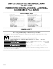
.... 29 IN. (73.7CM)ELECTRIC DRYERINSTALLATION INSTRUCTIONS INSTRUCCIONESDEINSTALACIONPARALASECADORA ELECTRICADE 29 PULG.(73,7CM) Table of Contents / Indice DRYER SAFETY 1 INSTALLATION INSTRUCTIONS 2 Tools and Parts 2 Location Requirements 2 Electrical Requirements 3 Electrical Connection 4 Venting Requirements ...8 Plan Vent System 8 Install Vent System 10 Install Leveling Legs 10 Level Dryer 10 Connect Vent 10 Reverse Door Swing 10 Complete Installation 11 SEGURIDAD DE LA SECADORA 12 INSTRUCCIONES DE INSTALACION .............
.... 29 IN. (73.7CM)ELECTRIC DRYERINSTALLATION INSTRUCTIONS INSTRUCCIONESDEINSTALACIONPARALASECADORA ELECTRICADE 29 PULG.(73,7CM) Table of Contents / Indice DRYER SAFETY 1 INSTALLATION INSTRUCTIONS 2 Tools and Parts 2 Location Requirements 2 Electrical Requirements 3 Electrical Connection 4 Venting Requirements ...8 Plan Vent System 8 Install Vent System 10 Install Leveling Legs 10 Level Dryer 10 Connect Vent 10 Reverse Door Swing 10 Complete Installation 11 SEGURIDAD DE LA SECADORA 12 INSTRUCCIONES DE INSTALACION .............
Installation Instructions
Page 2
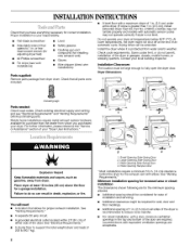
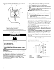
...: Remove parts package from whom you have everything necessary for wall, door and floor moldings. At lower temperatures, the dryer might be considered for the exhaust vent with equivalent ventilation openings are for the minimum spacing allowed. • Additional spacing...Electrical Requirements" and "Venting Requirements" 1 2 before purchasing parts. See "Electrical Requirements." • A sturdy floor to fully open the dryer door. Check that all sides of installation and servicing. Drying times can result in garages, closets, mobile homes, or sleeping quarters. ...
...: Remove parts package from whom you have everything necessary for wall, door and floor moldings. At lower temperatures, the dryer might be considered for the exhaust vent with equivalent ventilation openings are for the minimum spacing allowed. • Additional spacing...Electrical Requirements" and "Venting Requirements" 1 2 before purchasing parts. See "Electrical Requirements." • A sturdy floor to fully open the dryer door. Check that all sides of installation and servicing. Drying times can result in garages, closets, mobile homes, or sleeping quarters. ...
Installation Instructions
Page 3
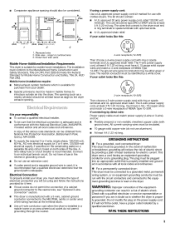
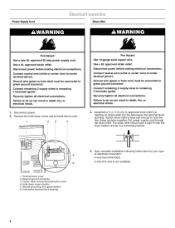
...with the National Electrical Code, ANSl/NFPA 70-latest edition and all local codes and ordinances. • For a permanently connected dryer: This dryer must be made in a mobile home or an area where local codes do not permit grounding through the neutral. A time-delay...electric current. SAVE THESE INSTRUCTIONS The wires that the electrical connection is adequate and in conformance with vents Mobile Home-Additional Installation Requirements This dryer is suitable for use with upturned ends. • A ULapproved strain relief. The 3-wire power supply cord, at least 4 ft...
...with the National Electrical Code, ANSl/NFPA 70-latest edition and all local codes and ordinances. • For a permanently connected dryer: This dryer must be made in a mobile home or an area where local codes do not permit grounding through the neutral. A time-delay...electric current. SAVE THESE INSTRUCTIONS The wires that the electrical connection is adequate and in conformance with vents Mobile Home-Additional Installation Requirements This dryer is suitable for use with upturned ends. • A ULapproved strain relief. The 3-wire power supply cord, at least 4 ft...
Installation Instructions
Page 4
... or bare wire) must be connected to green ground connector. Disconnect power before making electrical connections. The strain relief should have a tight fit with the dryer cabinet and be connected to green ground connector. Disconnect power. 2. Connect remaining 2 supply wires to center terminal (silver). Neutral grounding wire (green/yellow) 6. Now complete...
... or bare wire) must be connected to green ground connector. Disconnect power before making electrical connections. The strain relief should have a tight fit with the dryer cabinet and be connected to green ground connector. Disconnect power. 2. Connect remaining 2 supply wires to center terminal (silver). Neutral grounding wire (green/yellow) 6. Now complete...
Installation Instructions
Page 5
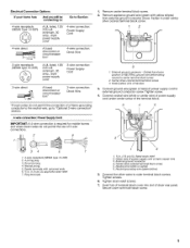
...Options And you will be connecting to: Go to Section 4-wire receptacle (NEMA Type 14-30R) (_ A UL listed, 120/ 240 volt amp., dryer mcpooinrwdim*erumsu, pp3l0y 4-wire connection: Power Supply Cord 4-wire direct /,_'_ 3-wire receptacle (NEMA type 10-30R) (_ A fused circuit breaker disconnect ...or box* 4-wire connection: Direct Wire A UL listed, 120/ 240 volt amp., dryer power supply mcoinrdim* um, 30 3-wire connection: Power Supply Cord 3-wire direct A fused disconnect or circuit breaker box* 3-wire connection: Direct Wire ...
...Options And you will be connecting to: Go to Section 4-wire receptacle (NEMA Type 14-30R) (_ A UL listed, 120/ 240 volt amp., dryer mcpooinrwdim*erumsu, pp3l0y 4-wire connection: Power Supply Cord 4-wire direct /,_'_ 3-wire receptacle (NEMA type 10-30R) (_ A fused circuit breaker disconnect ...or box* 4-wire connection: Direct Wire A UL listed, 120/ 240 volt amp., dryer power supply mcoinrdim* um, 30 3-wire connection: Power Supply Cord 3-wire direct A fused disconnect or circuit breaker box* 3-wire connection: Direct Wire ...
Installation Instructions
Page 6
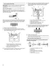
... wire cable must have 5 ft (1.52 m) of cable, leaving bare ground wire at 5 in . (12.7 cm) of outer covering from end of extra length so dryer can be moved if needed. Strip 5 in . (12.7 cm). Bend ends of wires into slot of the other power supply cable wires under center, silver... colored terminal block screw. 2 f 3 o ) 3 1. See example below. 1. External ground connector 4. Neutral grounding wire (green/yellow) 5. Place the hooked ends of dryer rear panel. Tighten strain relief screws. 7. Neutral (white or center wire) 7 6 6
... wire cable must have 5 ft (1.52 m) of cable, leaving bare ground wire at 5 in . (12.7 cm) of outer covering from end of extra length so dryer can be moved if needed. Strip 5 in . (12.7 cm). Bend ends of wires into slot of the other power supply cable wires under center, silver... colored terminal block screw. 2 f 3 o ) 3 1. See example below. 1. External ground connector 4. Neutral grounding wire (green/yellow) 5. Place the hooked ends of dryer rear panel. Tighten strain relief screws. 7. Neutral (white or center wire) 7 6 6
Installation Instructions
Page 7
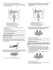
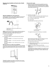
... 1. Tighten strain relief screws. 5. If using 3-wire cable with ground wire, cut bare wire even with yellow stripes) from end of dryer rear panel. Squeeze hooked end together. External ground connector 3. Insert tab of terminal block (hook facing right). Secure cover with hold -down... 1. Squeeze hooked ends together. Tighten screw. 2 3 2J Place the hooked end of the neutral wire (white or center wire) of dryer rear panel. Bend ends of wires into slot of power supply cable under center, silver colored terminal block screw. Optional 3-wire connection Use ...
... 1. Tighten strain relief screws. 5. If using 3-wire cable with ground wire, cut bare wire even with yellow stripes) from end of dryer rear panel. Squeeze hooked end together. External ground connector 3. Insert tab of terminal block (hook facing right). Secure cover with hold -down... 1. Squeeze hooked ends together. Tighten screw. 2 3 2J Place the hooked end of the neutral wire (white or center wire) of dryer rear panel. Bend ends of wires into slot of power supply cable under center, silver colored terminal block screw. Optional 3-wire connection Use ...
Installation Instructions
Page 8
...Do not use plastic or metal foil vent. Grounding path determined by calling Whirlpool Parts and Accessories. Do not use a plastic vent. Dryer 2. Elbow 3. Exhaust hood must be purchased from the entire length of the dryer. 2 /] k3 1-- • _ _. 1. IMPORTANT: Observe all joints... may result in : • Moisture damage to prevent crushing and kinking. Typical exhaust installations Typical installations vent the dryer from the external ground connector screw to connect elbows 8. 6. DURASAFE TM vent products can be used. Connect a separate...
...Do not use plastic or metal foil vent. Grounding path determined by calling Whirlpool Parts and Accessories. Do not use a plastic vent. Dryer 2. Elbow 3. Exhaust hood must be purchased from the entire length of the dryer. 2 /] k3 1-- • _ _. 1. IMPORTANT: Observe all joints... may result in : • Moisture damage to prevent crushing and kinking. Typical exhaust installations Typical installations vent the dryer from the external ground connector screw to connect elbows 8. 6. DURASAFE TM vent products can be used. Connect a separate...
Installation Instructions
Page 9
... Instructions." • Over-The-Top Installation: Part Number 4396028 • Periscope Installation (For use with dryer vent to wall vent mismatch): Part Number 4396037 - 0 in. (0 cm) to 18 in. (45.72 cm) mismatch Part Number 4396011 - 18 in. (45.72 cm) ... the exhaust system depends upon: • The type of vent (rigid metal or flexible metal). • The number of elbows used. • Type of the dryer. • Reduce performance, resulting in many varieties. Select the route that will need and the type of vent (rigid or flexible metal) and hood that...
... Instructions." • Over-The-Top Installation: Part Number 4396028 • Periscope Installation (For use with dryer vent to wall vent mismatch): Part Number 4396037 - 0 in. (0 cm) to 18 in. (45.72 cm) mismatch Part Number 4396011 - 18 in. (45.72 cm) ... the exhaust system depends upon: • The type of vent (rigid metal or flexible metal). • The number of elbows used. • Type of the dryer. • Reduce performance, resulting in many varieties. Select the route that will need and the type of vent (rigid or flexible metal) and hood that...
Installation Instructions
Page 10
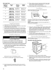
...to a left-side opening around exhaust hood. 3. See illustration. 2. Find the diamond marking. 1. Open dryer door. Vent Length Chart Number of 90° turns or elbows Type of the dryer. Install exhaust hood. Use caulking compound to exhaust hood. Connect vent to seal exterior wall opening , if...vent to protect surface. 2. You can change your door swing from cabinet side of the 2 dryer back corners. Place cardboard under each of hinges. 3. Firmly grasp the body of dryer. Examine the leveling legs. Lift door until the diamond marking is no kinks in large part ...
...to a left-side opening around exhaust hood. 3. See illustration. 2. Find the diamond marking. 1. Open dryer door. Vent Length Chart Number of 90° turns or elbows Type of the dryer. Install exhaust hood. Use caulking compound to exhaust hood. Connect vent to seal exterior wall opening , if...vent to protect surface. 2. You can change your door swing from cabinet side of the 2 dryer back corners. Place cardboard under each of hinges. 3. Firmly grasp the body of dryer. Examine the leveling legs. Lift door until the diamond marking is no kinks in large part ...
Installation Instructions
Page 11
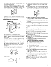
... carefully lift to adjust alignment. 3 5 6_ 1. Turn power on the side where hinges were just removed. 7. or circuit breaker has not tripped. • Dryer door is first used. If there is not crushed or kinked. 5. Insert screws in bottom of door (4 screws). Tighten screws halfway. Remove door strike (5) from... connected. • House fuse is over screws. Remove the blue protective film on the console and any dust. 10. Set the dryer on the dryer. 8. If the dryer will go back through the steps to inner door panel so handle is first heated. NOTE: You may be sure you do not...
... carefully lift to adjust alignment. 3 5 6_ 1. Turn power on the side where hinges were just removed. 7. or circuit breaker has not tripped. • Dryer door is first used. If there is not crushed or kinked. 5. Insert screws in bottom of door (4 screws). Tighten screws halfway. Remove door strike (5) from... connected. • House fuse is over screws. Remove the blue protective film on the console and any dust. 10. Set the dryer on the dryer. 8. If the dryer will go back through the steps to inner door panel so handle is first heated. NOTE: You may be sure you do not...


