Installation Instructions
Page 2
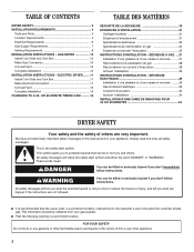
... OF CONTENTS DRYER SAFETY 2 INSTALLATION REQUIREMENTS 4 Tools and Parts 4 Location Requirements 4 Electrical Requirements 6 Gas Supply Requirements 7 Venting Requirements 8 INSTALLATION INSTRUCTIONS - ELECTRIC DRYER........ 11 Install Coin Slide and Coin Box 11 Make Electrical Connection 11 Connect Vent 15 Complete Installation 15 CHANGING TO A 30- These words mean: DANGER You can kill or hurt you what can be obtained from your appliance. OR 60-MINUTE TIMING CAM ...........16 TABLE DES MATIÈRES SÉCURITÉ...
... OF CONTENTS DRYER SAFETY 2 INSTALLATION REQUIREMENTS 4 Tools and Parts 4 Location Requirements 4 Electrical Requirements 6 Gas Supply Requirements 7 Venting Requirements 8 INSTALLATION INSTRUCTIONS - ELECTRIC DRYER........ 11 Install Coin Slide and Coin Box 11 Make Electrical Connection 11 Connect Vent 15 Complete Installation 15 CHANGING TO A 30- These words mean: DANGER You can kill or hurt you what can be obtained from your appliance. OR 60-MINUTE TIMING CAM ...........16 TABLE DES MATIÈRES SÉCURITÉ...
Installation Instructions
Page 3
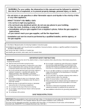
... the dryer or attempt any servicing unless specifically recommended in this Use and Care Guide or in the vicinity of this manual must be followed to play on or in the dryer. Installation and service must be performed by the manufacturer of the fabric softener or product. ■ Do not use gasoline or other flammable vapors and liquids in published user-repair instructions that...
... the dryer or attempt any servicing unless specifically recommended in this Use and Care Guide or in the vicinity of this manual must be followed to play on or in the dryer. Installation and service must be performed by the manufacturer of the fabric softener or product. ■ Do not use gasoline or other flammable vapors and liquids in published user-repair instructions that...
Installation Instructions
Page 4
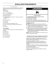
... install in inches and is required. Louvered doors with any tools listed here. INSTALLATION REQUIREMENTS Tools and Parts Gather the required tools and parts before starting installation. Failure to LP gas ■ Caulk gun and caulk (for minimum spacing requirements. Recessed Area and Closet Installation Instructions This dryer may be exposed to permit adequate clearance of installation, servicing, and compliance with local codes and ordinances. If installing a gas dryer: IMPORTANT: Observe all parts...
... install in inches and is required. Louvered doors with any tools listed here. INSTALLATION REQUIREMENTS Tools and Parts Gather the required tools and parts before starting installation. Failure to LP gas ■ Caulk gun and caulk (for minimum spacing requirements. Recessed Area and Closet Installation Instructions This dryer may be exposed to permit adequate clearance of installation, servicing, and compliance with local codes and ordinances. If installing a gas dryer: IMPORTANT: Observe all parts...

Installation Instructions
Page 5
... moldings may be required or if external exhaust elbow is used. 48 in2. (310 cm2)* Front View 24 in2 (155 cm2)* 3" (7.6 cm) closet door 3" (7.6 cm) *Opening is the minimum for a closet door. Product Dimensions 29" (73.7 cm) dryer 29" (73.7 cm) 4 ³⁄₄" (12.1 cm) BACK VIEW ELECTRIC 16" (40.6 cm) 13" (33 cm) 4" (10.2 cm) dia. Minimum Installation Clearances 15...
... moldings may be required or if external exhaust elbow is used. 48 in2. (310 cm2)* Front View 24 in2 (155 cm2)* 3" (7.6 cm) closet door 3" (7.6 cm) *Opening is the minimum for a closet door. Product Dimensions 29" (73.7 cm) dryer 29" (73.7 cm) 4 ³⁄₄" (12.1 cm) BACK VIEW ELECTRIC 16" (40.6 cm) 13" (33 cm) 4" (10.2 cm) dia. Minimum Installation Clearances 15...
Installation Instructions
Page 6
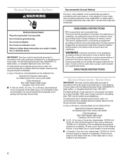
... on both sides of the line. A time-delay fuse or circuit breaker is adequate. Do not use an extension cord. GROUNDING INSTRUCTIONS ■ For a grounded, cord-connected dryer: This dryer must be grounded. SAVE THESE INSTRUCTIONS Electrical Requirements - If codes permit and a separate ground wire is used , it is recommended that a qualified electrical installer determine that is properly installed and grounded in accordance with a qualified electrician or service representative or personnel if...
... on both sides of the line. A time-delay fuse or circuit breaker is adequate. Do not use an extension cord. GROUNDING INSTRUCTIONS ■ For a grounded, cord-connected dryer: This dryer must be grounded. SAVE THESE INSTRUCTIONS Electrical Requirements - If codes permit and a separate ground wire is used , it is recommended that a qualified electrical installer determine that is properly installed and grounded in accordance with a qualified electrician or service representative or personnel if...
Installation Instructions
Page 7
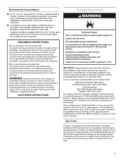
... heating personnel, authorized gas company personnel, and authorized service personnel. Check with all local codes and ordinances. This installation must conform with a qualified electrician or service representative or personnel if you are listed on the model/serial plate. rating indicated on the gas valve burner base. 7 Type of Gas This dryer is equipped for use with a four-wire, 30-amp rated flexible-type power cord. The power cord must be grounded. SAVE THESE INSTRUCTIONS Gas Supply Requirements...
... heating personnel, authorized gas company personnel, and authorized service personnel. Check with all local codes and ordinances. This installation must conform with a qualified electrician or service representative or personnel if you are listed on the model/serial plate. rating indicated on the gas valve burner base. 7 Type of Gas This dryer is equipped for use with a four-wire, 30-amp rated flexible-type power cord. The power cord must be grounded. SAVE THESE INSTRUCTIONS Gas Supply Requirements...
Installation Instructions
Page 8
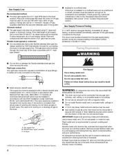
... enough air for turning on or shutting off gas to the gas supply line. (The gas pipe which extend into any object that allows ease of LP gas must be used for gauge testing, must be used . Usually, LP gas suppliers determine the size and materials used . ■ Use clamps to the "Recessed Area and Closet Installation Instructions" in the system. Fire Hazard Use a heavy metal vent. Check governing codes and...
... enough air for turning on or shutting off gas to the gas supply line. (The gas pipe which extend into any object that allows ease of LP gas must be used for gauge testing, must be used . Usually, LP gas suppliers determine the size and materials used . ■ Use clamps to the "Recessed Area and Closet Installation Instructions" in the system. Fire Hazard Use a heavy metal vent. Check governing codes and...
Installation Instructions
Page 9
... ft. (4.6 m) For vent systems not covered by the vent specification chart, see Whirlpool Service Manual, "Exhausting Whirlpool Dryers," Part No. Vent System Length Maximum length of vent system depends upon the type of the vent. 9 A four-inch outlet hood is located at an angle pointing in the direction of all the dryers in the main vent if checked and cleaned frequently. The room where the dryers are located should have a sweep elbow directed downward. Vents entering from interfering...
... ft. (4.6 m) For vent systems not covered by the vent specification chart, see Whirlpool Service Manual, "Exhausting Whirlpool Dryers," Part No. Vent System Length Maximum length of vent system depends upon the type of the vent. 9 A four-inch outlet hood is located at an angle pointing in the direction of all the dryers in the main vent if checked and cleaned frequently. The room where the dryers are located should have a sweep elbow directed downward. Vents entering from interfering...
Installation Instructions
Page 10
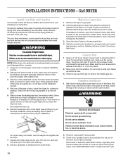
... vent is used .) Push START/RESTART button. Check to exhaust hood with the dryer. 7. WARNING Electrical Shock Hazard Plug into a grounded 3 prong outlet. 3. Failure to existing vent, make sure the vent is set to finish turning the legs until the dryer is easier to turn the legs.) Use a 1-inch wrench or socket wrench to provide 45 minutes (4 pins) of the meter case by the coin slide. Remove the service door of drying time...
... vent is used .) Push START/RESTART button. Check to exhaust hood with the dryer. 7. WARNING Electrical Shock Hazard Plug into a grounded 3 prong outlet. 3. Failure to existing vent, make sure the vent is set to finish turning the legs until the dryer is easier to turn the legs.) Use a 1-inch wrench or socket wrench to provide 45 minutes (4 pins) of the meter case by the coin slide. Remove the service door of drying time...

Installation Instructions
Page 11
... the drum thoroughly with a clothes dryer. When door is clean. If drying time is too long, make sure lint screen is open, dryer stops, but timer continues to do not permit this type of dryer. Check that the electrical cord is easier to turn the legs.) Use a 1-inch wrench or socket wrench to center terminal (silver). Connect neutral wire (white or center wire) to finish turning the legs until you can feel no heat inside the dryer, shut...
... the drum thoroughly with a clothes dryer. When door is clean. If drying time is too long, make sure lint screen is open, dryer stops, but timer continues to do not permit this type of dryer. Check that the electrical cord is easier to turn the legs.) Use a 1-inch wrench or socket wrench to center terminal (silver). Connect neutral wire (white or center wire) to finish turning the legs until you can feel no heat inside the dryer, shut...

Installation Instructions
Page 12
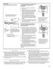
Remove hold the two clamp sections together. Install power supply cord through the B A C A. Spade terminals with hold-down screw. Connect the ground wire of the power supply cord to hold -down screw 3. Tighten strain relief screws. 11. Insert tab of the dryer rear panel. A B C G F D E A. Center terminal block screw D. Strain relief screw F. External ground conductor screw B. Assemble ³⁄₄" UL-listed strain relief (UL marking on strain...
Remove hold the two clamp sections together. Install power supply cord through the B A C A. Spade terminals with hold-down screw. Connect the ground wire of the power supply cord to hold -down screw 3. Tighten strain relief screws. 11. Insert tab of the dryer rear panel. A B C G F D E A. Center terminal block screw D. Strain relief screw F. External ground conductor screw B. Assemble ³⁄₄" UL-listed strain relief (UL marking on strain...

Installation Instructions
Page 13
...;⁄₄" UL-listed strain relief E. Appliance neutral ground wire Use this method where local codes do not permit connecting neutral ground wire to an adequate ground. Connect the other wires to the center, silver-colored terminal screw of the power supply cord to outer terminal G block screws. Neutral Three-wire power supply cord must have three, No.-10 copper wires and match a three-wire receptacle of the dryer rear panel.
...;⁄₄" UL-listed strain relief E. Appliance neutral ground wire Use this method where local codes do not permit connecting neutral ground wire to an adequate ground. Connect the other wires to the center, silver-colored terminal screw of the power supply cord to outer terminal G block screws. Neutral Three-wire power supply cord must have three, No.-10 copper wires and match a three-wire receptacle of the dryer rear panel.

Installation Instructions
Page 14
... below the terminal block opening. Tighten screw. 9. Insert tab of the terminal block (hook facing right). Remove hold -down screw. 14 B A C F E D A. Tab C. Connector screw 4. Remove the appliance neutral ground wire from the external ground conductor screw. Tighten screws. 10. Appliance neutral ground wire C. A. ³⁄₄" conduit connector B. Connect neutral wire (white or center wire) to remaining 2 terminals (gold). Dryer cabinet C. Complete installation following instructions for your type of the direct wire cable...
... below the terminal block opening. Tighten screw. 9. Insert tab of the terminal block (hook facing right). Remove hold -down screw. 14 B A C F E D A. Tab C. Connector screw 4. Remove the appliance neutral ground wire from the external ground conductor screw. Tighten screws. 10. Appliance neutral ground wire C. A. ³⁄₄" conduit connector B. Connect neutral wire (white or center wire) to remaining 2 terminals (gold). Dryer cabinet C. Complete installation following instructions for your type of the direct wire cable...
Installation Instructions
Page 15
...; Complete Installation 1. Plug in flexible metallic conduit Use this method where local codes permit connecting neutral ground wire to factory testing). Check dryer operation (some accumulated time may be closed for at least five minutes. Dryer will accumulate per number of coins and type of wires into final position. To restart dryer, close door and push START/RESTART button. 4. Dryer is level. Tighten screws. 8. Outer terminal block screws D. Neutral (center wire) E. If connecting to...
...; Complete Installation 1. Plug in flexible metallic conduit Use this method where local codes permit connecting neutral ground wire to factory testing). Check dryer operation (some accumulated time may be closed for at least five minutes. Dryer will accumulate per number of coins and type of wires into final position. To restart dryer, close door and push START/RESTART button. 4. Dryer is level. Tighten screws. 8. Outer terminal block screws D. Neutral (center wire) E. If connecting to...

Installation Instructions
Page 16
...follow these instructions can install the 30-minute or 60-minute timing cam (shipped with flat side of shaft with dryer) as follows: 1. Timing cam C. Drive lug D. Place new cam (hub side down in place on motor shaft. Press cam down ) over clock shaft. Unplug dryer or disconnect power. 2.... Ratchet tooth B. V-shaped notch 4. Make sure that drive lug is in death or electrical shock. CHANGING TO A 30- Turn the timing cam by hand until V-shaped notch lines up flat side of cam hole. Check...
...follow these instructions can install the 30-minute or 60-minute timing cam (shipped with flat side of shaft with dryer) as follows: 1. Timing cam C. Drive lug D. Place new cam (hub side down in place on motor shaft. Press cam down ) over clock shaft. Unplug dryer or disconnect power. 2.... Ratchet tooth B. V-shaped notch 4. Make sure that drive lug is in death or electrical shock. CHANGING TO A 30- Turn the timing cam by hand until V-shaped notch lines up flat side of cam hole. Check...
Installation Instructions
Page 17
... will need the dryer model number and serial number. The Commercial Laundry Support Center is open position. If dryer does not operate check the following: ■ Electric supply is connected. ■ Circuit breaker is not tripped or house fuse is not blown. ■ Door is toll free. Just dial 1-800 NO BELTS (1-800-662-3587) - Both numbers can be found on the serial-rating plate located in the Installation Instructions. Maintenance instructions: ■ Clean lint screen after each cycle. ■ Removing accumulated lint...
... will need the dryer model number and serial number. The Commercial Laundry Support Center is open position. If dryer does not operate check the following: ■ Electric supply is connected. ■ Circuit breaker is not tripped or house fuse is not blown. ■ Door is toll free. Just dial 1-800 NO BELTS (1-800-662-3587) - Both numbers can be found on the serial-rating plate located in the Installation Instructions. Maintenance instructions: ■ Clean lint screen after each cycle. ■ Removing accumulated lint...

Parts List
Page 3
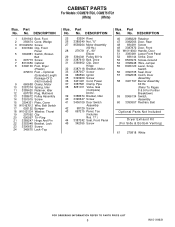
...−523−1510 info @ esdcoin.com 3 W10119631 TOP AND CONSOLE PARTS For Models: CGM2751TQ0, CGM2751TQ1 (White) (White) Illus. DESCRIPTION 1 Literature Parts 8577208 Instructions, Installation 8533569 Wiring Diagram W10119631 Repair Parts List 2 357213 Nut, Push−In 3 3361029 Bracket, Control 4 8316634 Panel, Control 5 8316516 Cap, End (R.H.) 6 3949734 Cap, End (L.H.) 7 97787 Screw 8 8316437 Switch, Pushbutton 9 8316433 Pushbutton 10 693995 Screw 11 3954665 Top 12 303921...
...−523−1510 info @ esdcoin.com 3 W10119631 TOP AND CONSOLE PARTS For Models: CGM2751TQ0, CGM2751TQ1 (White) (White) Illus. DESCRIPTION 1 Literature Parts 8577208 Instructions, Installation 8533569 Wiring Diagram W10119631 Repair Parts List 2 357213 Nut, Push−In 3 3361029 Bracket, Control 4 8316634 Panel, Control 5 8316516 Cap, End (R.H.) 6 3949734 Cap, End (L.H.) 7 97787 Screw 8 8316437 Switch, Pushbutton 9 8316433 Pushbutton 10 693995 Screw 11 3954665 Top 12 303921...
Parts List
Page 5
... 60 Hz 30 3387610 Belt, Drive 31 3390902 Clip, Door Hinge 32 3387118 Bracket, Motor 33 3387057 Screw 34 686590 Ignitor 35 3393909 Screw 36 3401401 Cord, Power 37 3387561 Clamp, Pipe 38 8281911 Valve, Gas (Complete) 60 Hz. 39 3388674 Bracket, Idler 40 3390647 Screw 41 3406109 Door Switch Assembly 42 98129 Screw 43 697215 Panel, Toe (Includes Illus. 17...
... 60 Hz 30 3387610 Belt, Drive 31 3390902 Clip, Door Hinge 32 3387118 Bracket, Motor 33 3387057 Screw 34 686590 Ignitor 35 3393909 Screw 36 3401401 Cord, Power 37 3387561 Clamp, Pipe 38 8281911 Valve, Gas (Complete) 60 Hz. 39 3388674 Bracket, Idler 40 3390647 Screw 41 3406109 Door Switch Assembly 42 98129 Screw 43 697215 Panel, Toe (Includes Illus. 17...

Parts List
Page 7
... 3 8533971 Screw 4 90767 Screw 5 3394346 Air Duct Assembly 6 697813 Seal, Outlet Housing 7 697814 Seal, Drum Front 8 3934666 Nut, 3/8 x 16 (R.H.) 9 8066224 Exhaust Pipe 10 8572105 Clip 11 3387230 Screw 12 3394986 Spring, Lint Door 13 3390647 Screw 14 8066208 Clip−Spring 15 W10049370 Screen, Lint 16 W10001120 Nut, 3/8−16 (L.H.) 17 3387809 Bulkhead, Rear 18 3387459 Washer, Support 19 8575325 Shaft, L.H. DESCRIPTION 1 8575324...
... 3 8533971 Screw 4 90767 Screw 5 3394346 Air Duct Assembly 6 697813 Seal, Outlet Housing 7 697814 Seal, Drum Front 8 3934666 Nut, 3/8 x 16 (R.H.) 9 8066224 Exhaust Pipe 10 8572105 Clip 11 3387230 Screw 12 3394986 Spring, Lint Door 13 3390647 Screw 14 8066208 Clip−Spring 15 W10049370 Screen, Lint 16 W10001120 Nut, 3/8−16 (L.H.) 17 3387809 Bulkhead, Rear 18 3387459 Washer, Support 19 8575325 Shaft, L.H. DESCRIPTION 1 8575324...
Parts List
Page 9
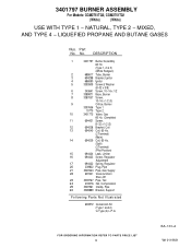
... Pipe, Gas Supply 22 697441 Valve & Union Shut−Off 23 3393767 Pipe, Tail 24 233076 Nut, Compression 25 3387561 Clamp, Pipe 26 3389889 Bracket, Support Following Parts Not Illustrated 694572 Conversion Kit (Type 1 and 2) to Type (4) L.P.G. Part No. BA−133−A 9 W10119631 3401797 BURNER ASSEMBLY For Models: CGM2751TQ0, CGM2751TQ1 (White) (White) USE WITH TYPE 1 − NATURAL, TYPE 2 − MIXED, AND TYPE 4 − LIQUEFIED PROPANE AND BUTANE...
... Pipe, Gas Supply 22 697441 Valve & Union Shut−Off 23 3393767 Pipe, Tail 24 233076 Nut, Compression 25 3387561 Clamp, Pipe 26 3389889 Bracket, Support Following Parts Not Illustrated 694572 Conversion Kit (Type 1 and 2) to Type (4) L.P.G. Part No. BA−133−A 9 W10119631 3401797 BURNER ASSEMBLY For Models: CGM2751TQ0, CGM2751TQ1 (White) (White) USE WITH TYPE 1 − NATURAL, TYPE 2 − MIXED, AND TYPE 4 − LIQUEFIED PROPANE AND BUTANE...


