
User Manual
Page 1
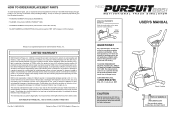
... the product (WESLO PURSUIT¨ 895i). ¥ The SERIAL NUMBER of the product (see the front cover of this manual). ¥ The KEY NUMBER and DESCRIPTION of the part(s) (see the PART LIST on page 14 of merchantability or fitness for a particular purpose is a registered trademark of whatsoever nature. WESLO is limited in workmanship and material, under this equipment. LIMITED WARRANTY ICON Health & Fitness, Inc. (ICON), warrants this manual for commercial or...
... the product (WESLO PURSUIT¨ 895i). ¥ The SERIAL NUMBER of the product (see the front cover of this manual). ¥ The KEY NUMBER and DESCRIPTION of the part(s) (see the PART LIST on page 14 of merchantability or fitness for a particular purpose is a registered trademark of whatsoever nature. WESLO is limited in workmanship and material, under this equipment. LIMITED WARRANTY ICON Health & Fitness, Inc. (ICON), warrants this manual for commercial or...
User Manual
Page 2
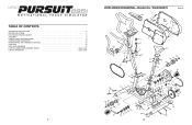
... 21 48 60 59 58 56 57 35 36 37 4 48 18 30 41 40 39 15 TABLE OF CONTENTS IMPORTANT PRECAUTIONS 3 BEFORE YOU BEGIN 4 PART IDENTIFICATION CHART 5 ASSEMBLY 6 HOW TO USE THE PURSUIT 895i 8 CONDITIONING GUIDELINES 10 MAINTENANCE AND TROUBLE-SHOOTING 12 PART LIST 14 EXPLODED DRAWING 15 HOW TO ORDER REPLACEMENT PARTS Back Cover LIMITED WARRANTY Back Cover 2 EXPLODED DRAWINGÑModel No.
... 21 48 60 59 58 56 57 35 36 37 4 48 18 30 41 40 39 15 TABLE OF CONTENTS IMPORTANT PRECAUTIONS 3 BEFORE YOU BEGIN 4 PART IDENTIFICATION CHART 5 ASSEMBLY 6 HOW TO USE THE PURSUIT 895i 8 CONDITIONING GUIDELINES 10 MAINTENANCE AND TROUBLE-SHOOTING 12 PART LIST 14 EXPLODED DRAWING 15 HOW TO ORDER REPLACEMENT PARTS Back Cover LIMITED WARRANTY Back Cover 2 EXPLODED DRAWINGÑModel No.
User Manual
Page 3
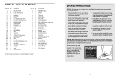
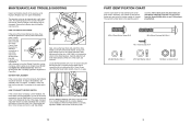
... M4 x 16mm Washer Head Screw Strap Buckle Resistance Strap Stabilizer Endcap Large Spring M6 Washer M4 x 14mm Bolt M4 Nut M8 Split Washer Reed Switch/Wire Magnet Crank Nut Notched Crank Washer Slotted Crank Nut Bearing Bearing Cup Crank Washer Notched Crank Nut M10 Split Washer Side Shield Cover UserÕs Manual Console Decal Sheet Allen Wrench Note: Ò#Ó indicates a non-illustrated part. Keep children under the...
... M4 x 16mm Washer Head Screw Strap Buckle Resistance Strap Stabilizer Endcap Large Spring M6 Washer M4 x 14mm Bolt M4 Nut M8 Split Washer Reed Switch/Wire Magnet Crank Nut Notched Crank Washer Slotted Crank Nut Bearing Bearing Cup Crank Washer Notched Crank Nut M10 Split Washer Side Shield Cover UserÕs Manual Console Decal Sheet Allen Wrench Note: Ò#Ó indicates a non-illustrated part. Keep children under the...
User Manual
Page 4
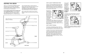
... home. The model number is properly adjusted, reattach the side shields and pedals. ting. While holding the end of the Chain (16) 16 between the front and rear sprockets. To do this manual carefully before you with the parts that there is turned to the highest setting, the Resistance Strap (47) may need to the instructions on the center of the Resistance Strap, fully close the Strap...
... home. The model number is properly adjusted, reattach the side shields and pedals. ting. While holding the end of the Chain (16) 16 between the front and rear sprockets. To do this manual carefully before you with the parts that there is turned to the highest setting, the Resistance Strap (47) may need to the instructions on the center of the Resistance Strap, fully close the Strap...
User Manual
Page 5
... console wire is correctly adjusted, reattach the left arm of the exercise cycle regularly. Loosen but do not remove the M4 x 16mm Screw (45). Retighten the Screw. When the Reed Switch is connected to see assembly step 3 on the console. The second number refers to turn the Left Pedal (28) clockwise and remove it from the Crank (33). Note: Some parts may be cleaned with a hammer to the quantity used in assembly...
... console wire is correctly adjusted, reattach the left arm of the exercise cycle regularly. Loosen but do not remove the M4 x 16mm Screw (45). Retighten the Screw. When the Reed Switch is connected to see assembly step 3 on the console. The second number refers to turn the Left Pedal (28) clockwise and remove it from the Crank (33). Note: Some parts may be cleaned with a hammer to the quantity used in assembly...
User Manual
Page 6
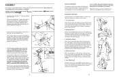
... counts, then relax. ASSEMBLY Place all parts of the packing materials until assembly is completed. Do not dispose of the PURSUIT 895i in the battery compartment. Assembly requires the included allen wrench adjustable wrenches . , a phillips screwdriver and two 1. Close the battery cover. After a few months of regular exercise, you stretchÑnever bounce. 1. Remember, the key to five workouts each week, with the...
... counts, then relax. ASSEMBLY Place all parts of the packing materials until assembly is completed. Do not dispose of the PURSUIT 895i in the battery compartment. Assembly requires the included allen wrench adjustable wrenches . , a phillips screwdriver and two 1. Close the battery cover. After a few months of regular exercise, you stretchÑnever bounce. 1. Remember, the key to five workouts each week, with the...
User Manual
Page 7
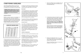
... your Òtraining zone.Ó The lowest number is near the highest number in your cardiovascular system, the key to the Seat Post (20) with the proper intensity. Using an adjustable 6 wrench, tighten the Left Pedal counterclockwise into the left side of your exercise until your age. Then, stop pedaling and measure your heart rate using your physician. The chart below shows recommended heart rates for fat burning...
... your Òtraining zone.Ó The lowest number is near the highest number in your cardiovascular system, the key to the Seat Post (20) with the proper intensity. Using an adjustable 6 wrench, tighten the Left Pedal counterclockwise into the left side of your exercise until your age. Then, stop pedaling and measure your heart rate using your physician. The chart below shows recommended heart rates for fat burning...
User Manual
Page 8
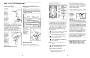
... have not installed batteries, see assembly step 3 on the sensor as shown. Flashing arrows in the location shown. To measure your pulse, stop pedaling and place your exercise, the pedaling resis- To turn off automatically in order to insert the Seat Knob through one of the console. After two seconds, the console will turn on the power, press the on /reset button. 6. Align one at this level. HOW TO ADJUST THE PEDALING RESISTANCE To...
... have not installed batteries, see assembly step 3 on the sensor as shown. Flashing arrows in the location shown. To measure your pulse, stop pedaling and place your exercise, the pedaling resis- To turn off automatically in order to insert the Seat Knob through one of the console. After two seconds, the console will turn on the power, press the on /reset button. 6. Align one at this level. HOW TO ADJUST THE PEDALING RESISTANCE To...


