

English Manual
Page 4
Never remove the motor hood un- Servicing other than the procedures in the storage position. 23. SAVE THESE INSTRUCTIONS 4 Do not attempt to raise, lower, or move the treadmill until it is properly assembled. (See ASSEMBLY on page 6, and HOW TO FOLD AND MOVE THE TREADMILL on page 17.) You must...you feel faint or if you experience pain while exercising, stop immediately and cool down. Always unplug the power cord immediately after use this treadmill in serious injury or death. Always remove the key, unplug the power cord, and switch the reset/off circuit breaker to do so by...
Never remove the motor hood un- Servicing other than the procedures in the storage position. 23. SAVE THESE INSTRUCTIONS 4 Do not attempt to raise, lower, or move the treadmill until it is properly assembled. (See ASSEMBLY on page 6, and HOW TO FOLD AND MOVE THE TREADMILL on page 17.) You must...you feel faint or if you experience pain while exercising, stop immediately and cool down. Always unplug the power cord immediately after use this treadmill in serious injury or death. Always remove the key, unplug the power cord, and switch the reset/off circuit breaker to do so by...
English Manual
Page 18
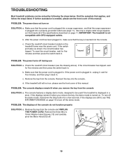
... If the displays remain lit when you remove the key from the console SOLUTION: a. b. Check the reset/off . 53 18 If the treadmill still will not run, please see the front cover of the specifications described on SOLUTION: a. The console features a display demo mode, designed ... on page 11. Remove the three M4.2 x a 19mm Washer Head Screws (13) and carefully 13 pivot the Motor Hood (53) off circuit breaker located on . c. IMPORTANT: The treadmill is displayed in . b. If further assistance is plugged in a store. PROBLEM: The power does not turn off...
... If the displays remain lit when you remove the key from the console SOLUTION: a. b. Check the reset/off . 53 18 If the treadmill still will not run, please see the front cover of the specifications described on SOLUTION: a. The console features a display demo mode, designed ... on page 11. Remove the three M4.2 x a 19mm Washer Head Screws (13) and carefully 13 pivot the Motor Hood (53) off circuit breaker located on . c. IMPORTANT: The treadmill is displayed in . b. If further assistance is plugged in a store. PROBLEM: The power does not turn off...

English Manual
Page 19
...sary, loosen the M4.2 x 19mm Screw (1), move the 54 Reed Switch slightly, and then retighten the Screw. 44 Reattach the Motor Hood (not shown), and run the treadmill for a correct View speed reading. Remove the key and UNPLUG THE POWER CORD. When the walking belt is about 1/8 in the... the walking belt is aligned with the Reed Switch. 1/8 in . (5 to check for a few seconds, re-insert the key. The treadmill will recalibrate the incline system. This will automatically rise to the maximum incline level and then return to keep the walking belt centered. While the...
...sary, loosen the M4.2 x 19mm Screw (1), move the 54 Reed Switch slightly, and then retighten the Screw. 44 Reattach the Motor Hood (not shown), and run the treadmill for a correct View speed reading. Remove the key and UNPLUG THE POWER CORD. When the walking belt is about 1/8 in the... the walking belt is aligned with the Reed Switch. 1/8 in . (5 to check for a few seconds, re-insert the key. The treadmill will recalibrate the incline system. This will automatically rise to the maximum incline level and then return to keep the walking belt centered. While the...

English Manual
Page 22
... Lift Frame/Roller Ground Wire Incline Motor Idler Roller Bracket Drive Motor Motor Bracket Lift Frame Cable Tie Lift Frame 5 mm Hex Key Power Cord Controller Grommet Reset/Off Circuit Breaker Belly Pan Latch Insert Left Crosswalk Arm Latch Pin Assembly Left Upright #10 x 3/4" Screw Crosswalk Arm Insert Right Crosswalk Arm Upright Wire Right Upright Bolt...
... Lift Frame/Roller Ground Wire Incline Motor Idler Roller Bracket Drive Motor Motor Bracket Lift Frame Cable Tie Lift Frame 5 mm Hex Key Power Cord Controller Grommet Reset/Off Circuit Breaker Belly Pan Latch Insert Left Crosswalk Arm Latch Pin Assembly Left Upright #10 x 3/4" Screw Crosswalk Arm Insert Right Crosswalk Arm Upright Wire Right Upright Bolt...

English Manual
Page 23
For information about ordering replacement parts, see the back cover of this manual. *These parts are subject to change without notice. Description Incline Stop Bracket 8" Blue Wire, 2F 6" Blue Wire, M/F 6" Red Wire, M/F 6" Black Wire, M/F 8" Green Wire, F/Ring Userʼs Manual Note: Specifications are not illustrated. 23 Qty. 108 1 * - * - * - * - * - * - Key No. Qty. 101 1 102 1 103 2 104 2 105 1 106 2 107 1 Description Hex Key Lift Frame/Base Ground Wire Frame Cap Base Foot Spacer 4 mm Hex Key M8 Locknut Motor Tension Washer Key No.
For information about ordering replacement parts, see the back cover of this manual. *These parts are subject to change without notice. Description Incline Stop Bracket 8" Blue Wire, 2F 6" Blue Wire, M/F 6" Red Wire, M/F 6" Black Wire, M/F 8" Green Wire, F/Ring Userʼs Manual Note: Specifications are not illustrated. 23 Qty. 108 1 * - * - * - * - * - * - Key No. Qty. 101 1 102 1 103 2 104 2 105 1 106 2 107 1 Description Hex Key Lift Frame/Base Ground Wire Frame Cap Base Foot Spacer 4 mm Hex Key M8 Locknut Motor Tension Washer Key No.

English Manual
Page 28
... number and description of the replacement part(s) (see the front cover of enjoyment or use and service conditions. Go to the original purchaser. The drive motor is under normal use , or costs of the purchase date to the terms set forth above is authorized by ICON. Parts and labor are made...
... number and description of the replacement part(s) (see the front cover of enjoyment or use and service conditions. Go to the original purchaser. The drive motor is under normal use , or costs of the purchase date to the terms set forth above is authorized by ICON. Parts and labor are made...


