
English Manual
Page 1
... the serial number in this manual before using this manual for reference. Importer: Comercializadora México Americana, S. de C.V. CMA-910911-9L0 Call: 5899 12 00 Web: www.iconservice.com Electrical Specifications: Requires four 1.5V AA batteries (see page 16) CAUTION Read all precautions and instructions in the space above for future reference. USER'S MANUAL If you have questions, or if parts are...
... the serial number in this manual before using this manual for reference. Importer: Comercializadora México Americana, S. de C.V. CMA-910911-9L0 Call: 5899 12 00 Web: www.iconservice.com Electrical Specifications: Requires four 1.5V AA batteries (see page 16) CAUTION Read all precautions and instructions in the space above for future reference. USER'S MANUAL If you have questions, or if parts are...
English Manual
Page 2
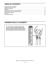
If a decal is a registered trademark of the warning decal(s). WESLO is missing or illegible, go to www.iconservice.com and request a free replacement decal. Note: The decal(s) may not be shown at actual size. Apply the decal in the location shown. TABLE OF CONTENTS WARNING DECAL PLACEMENT 2 IMPORTANT PRECAUTIONS 3 BEFORE YOU BEGIN 4 ASSEMBLY 5 HOW TO USE THE ELLIPTICAL EXERCISER 12 MAINTENANCE AND TROUBLESHOOTING 16 EXERCISE GUIDELINES 17 PART LIST 21 EXPLODED DRAWING 22 WARNING DECAL PLACEMENT This drawing shows the location(s) of ICON IP, Inc. 2
If a decal is a registered trademark of the warning decal(s). WESLO is missing or illegible, go to www.iconservice.com and request a free replacement decal. Note: The decal(s) may not be shown at actual size. Apply the decal in the location shown. TABLE OF CONTENTS WARNING DECAL PLACEMENT 2 IMPORTANT PRECAUTIONS 3 BEFORE YOU BEGIN 4 ASSEMBLY 5 HOW TO USE THE ELLIPTICAL EXERCISER 12 MAINTENANCE AND TROUBLESHOOTING 16 EXERCISE GUIDELINES 17 PART LIST 21 EXPLODED DRAWING 22 WARNING DECAL PLACEMENT This drawing shows the location(s) of ICON IP, Inc. 2
English Manual
Page 3
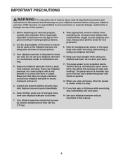
... manual and all warnings on your elliptical exerciser before using your elliptical exerciser in general. 12. Keep children under age 12 and pets away from moisture and dust. Hold the handgrip pulse sensor or the upper body arms when mounting, dismounting, or using your physician. The pulse sensor is the responsibility of the owner to a stop. 13. If you stop immediately and cool down. 14. Replace any exercise program...
... manual and all warnings on your elliptical exerciser before using your elliptical exerciser in general. 12. Keep children under age 12 and pets away from moisture and dust. Hold the handgrip pulse sensor or the upper body arms when mounting, dismounting, or using your physician. The pulse sensor is the responsibility of the owner to a stop. 13. If you stop immediately and cool down. 14. Replace any exercise program...
English Manual
Page 4
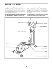
... parts that moves your knees and ankles. Pulse Sensor Water Bottle Holder* Console Upper Body Arm Shield Pedal Disc Wheel Leveling Foot Pedal *Water bottle is an incredibly smooth exerciser that are shown on the front cover of the serial number decal are labeled in a natural elliptical path, minimizing the impact on your feet in the drawing below. BEFORE YOU BEGIN Thank you use the elliptical exerciser...
... parts that moves your knees and ankles. Pulse Sensor Water Bottle Holder* Console Upper Body Arm Shield Pedal Disc Wheel Leveling Foot Pedal *Water bottle is an incredibly smooth exerciser that are shown on the front cover of the serial number decal are labeled in a natural elliptical path, minimizing the impact on your feet in the drawing below. BEFORE YOU BEGIN Thank you use the elliptical exerciser...
English Manual
Page 5
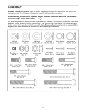
... Button Bolt (11)-4 M10 x 76mm Button Bolt (74)-2 M10 x 60mm Button Screw (67)-2 M10 x 75mm Carriage Bolt (58)-2 5 The number in the hardware kit, check to see if it has been preassembled. Do not dispose of the elliptical exerciser in a cleared area and remove the packing materials. In addition to identify the small parts needed for assembly. The number following the key number is the quantity needed for assembly...
... Button Bolt (11)-4 M10 x 76mm Button Bolt (74)-2 M10 x 60mm Button Screw (67)-2 M10 x 75mm Carriage Bolt (58)-2 5 The number in the hardware kit, check to see if it has been preassembled. Do not dispose of the elliptical exerciser in a cleared area and remove the packing materials. In addition to identify the small parts needed for assembly. The number following the key number is the quantity needed for assembly...
English Manual
Page 6
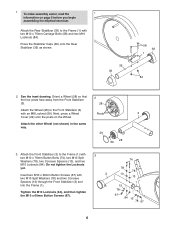
... same way. 29 59 28 3. Insert two M10 x 60mm Button Screws (67) with two M10 x 75mm Carriage Bolts (58) and two M10 Locknuts (84). Do not tighten the Locknuts yet. Next, press a Wheel Posts 3 Cover (29) onto the posts on page 5 before you begin assembling the elliptical exerciser. Attach the Rear Stabilizer (35) to the Frame (1) with an M8 Locknut (59...
... same way. 29 59 28 3. Insert two M10 x 60mm Button Screws (67) with two M10 x 75mm Carriage Bolts (58) and two M10 Locknuts (84). Do not tighten the Locknuts yet. Next, press a Wheel Posts 3 Cover (29) onto the posts on page 5 before you begin assembling the elliptical exerciser. Attach the Rear Stabilizer (35) to the Frame (1) with an M8 Locknut (59...

English Manual
Page 7
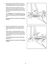
... Washers (79). 4. Attach the other Pedal (not shown) to the Lower Wire Harness (38). Avoid pinching the Wire Harnesses (18, 38) 2 79 73 18 38 79 73 79 73 1 5. Attach a Pedal (19) to the Left 5 Pedal Arm with three M4 x 19mm Screws (68) and three Star Washers (85). Tip: Avoid pinching the Wire Harnesses (18, 38). Do not tighten the Patch Screws yet.
... Washers (79). 4. Attach the other Pedal (not shown) to the Lower Wire Harness (38). Avoid pinching the Wire Harnesses (18, 38) 2 79 73 18 38 79 73 79 73 1 5. Attach a Pedal (19) to the Left 5 Pedal Arm with three M4 x 19mm Screws (68) and three Star Washers (85). Tip: Avoid pinching the Wire Harnesses (18, 38). Do not tighten the Patch Screws yet.

English Manual
Page 8
...) through the Upper Body Legs and the Upright. Identify the Left and Right Upper Body Legs (6, 7), which are marked with "Left" and "Right" stickers. Tighten an M8 x 23mm Button Screw (65), an M8 Washer (64) and a Pivot Cover (14) into each end of the Pivot Axle. 6 Hexagonal Holes Grease 27 6 18 27 Grease 2 16 7 Avoid damaging the Upper Wire Harness (18) 7. Slide...
...) through the Upper Body Legs and the Upright. Identify the Left and Right Upper Body Legs (6, 7), which are marked with "Left" and "Right" stickers. Tighten an M8 x 23mm Button Screw (65), an M8 Washer (64) and a Pivot Cover (14) into each end of the Pivot Axle. 6 Hexagonal Holes Grease 27 6 18 27 Grease 2 16 7 Avoid damaging the Upper Wire Harness (18) 7. Slide...
English Manual
Page 9
... time working the Left Pedal Arm onto the Left Crank Arm (42). Apply a generous amount of grease to the axle on the Left Upper Body Leg (6). Then, apply grease to the Left Upper Body Leg (6) with an M8 x 25mm Patch Screw (70) and an M8 Large Washer (81). 6 See step 4. Repeat this step for the other side of the elliptical exerciser. 8 6 Grease 20 21 Grease 42 45 9. Tighten the...
... time working the Left Pedal Arm onto the Left Crank Arm (42). Apply a generous amount of grease to the axle on the Left Upper Body Leg (6). Then, apply grease to the Left Upper Body Leg (6) with an M8 x 25mm Patch Screw (70) and an M8 Large Washer (81). 6 See step 4. Repeat this step for the other side of the elliptical exerciser. 8 6 Grease 20 21 Grease 42 45 9. Tighten the...

English Manual
Page 10
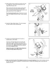
... M8 x 38mm Button Bolts (94) and two M8 Locknuts (59). Orient the Left Pulse Bar so that the Locknuts are in the Upright (2). Have another person hold the Left Pulse Bar (90) near the Upright (2). Locate the wire tie in the hexagonal holes. Make sure that the hexagonal holes are recommended. Repeat this step for the Right Pulse Bar (91). 10 Wire Ties 94...
... M8 x 38mm Button Bolts (94) and two M8 Locknuts (59). Orient the Left Pulse Bar so that the Locknuts are in the Upright (2). Have another person hold the Left Pulse Bar (90) near the Upright (2). Locate the wire tie in the hexagonal holes. Make sure that the hexagonal holes are recommended. Repeat this step for the Right Pulse Bar (91). 10 Wire Ties 94...
English Manual
Page 11
... a mat under the elliptical exerciser. 11 Then, connect the green console ground wire to the Upper Wire Harness (18). Attach the Water Bottle Holder (17) to the blue and orange Pulse Wires (96). Insert the Left Upper Body Arm (4) into the Left Upper Body Leg (6). Note: Some hardware may be left over after assembly is 14 marked with two M8 x 45mm Button Bolts (11) and two...
... a mat under the elliptical exerciser. 11 Then, connect the green console ground wire to the Upper Wire Harness (18). Attach the Water Bottle Holder (17) to the blue and orange Pulse Wires (96). Insert the Left Upper Body Arm (4) into the Left Upper Body Leg (6). Note: Some hardware may be left over after assembly is 14 marked with two M8 x 45mm Button Bolts (11) and two...
English Manual
Page 12
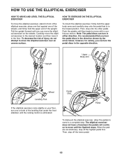
... position. To decrease the risk of injury, do not attempt to move the elliptical exerciser to the desired location and then lower it to a complete stop. Then, step off the highest pedal first. Then, step onto the other pedal. Upright Upper Body Arm Wheel Leveling Foot If the elliptical exerciser rocks slightly on the wheels. Note: The pedal discs can move the elliptical exerciser on your floor, turn in either direction.
... position. To decrease the risk of injury, do not attempt to move the elliptical exerciser to the desired location and then lower it to a complete stop. Then, step off the highest pedal first. Then, step onto the other pedal. Upright Upper Body Arm Wheel Leveling Foot If the elliptical exerciser rocks slightly on the wheels. Note: The pedal discs can move the elliptical exerciser on your floor, turn in either direction.
English Manual
Page 13
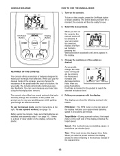
... heart rate using the console, make your pedaling speed, in the workout instead of the display indicates the target speed. When you pedal, change the resistance of a button. As you use . 2. Note: After you through an effective workout. 4. The display can even measure your pedaling pace while guiding you press the buttons, it will then be selected. Before using the handgrip pulse sensors. Speed-This mode shows your workouts more effective. Note: When you turn on the console, press...
... heart rate using the console, make your pedaling speed, in the workout instead of the display indicates the target speed. When you pedal, change the resistance of a button. As you use . 2. Note: After you through an effective workout. 4. The display can even measure your pedaling pace while guiding you press the buttons, it will then be selected. Before using the handgrip pulse sensors. Speed-This mode shows your workouts more effective. Note: When you turn on the console, press...
English Manual
Page 14
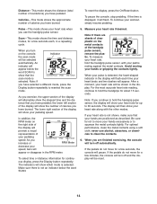
... shown in a repeating cycle. After a moment, your pedaling speed. If the pedals do not move your heart rate if desired. To pause the console, stop pedaling. As you exercise, the upper section of the display will then show the number of your heart rate when you use alcohol, abrasives, or chemicals to hold the handgrip pulse sensor, with the other modes. To measure your palms resting against the...
... shown in a repeating cycle. After a moment, your pedaling speed. If the pedals do not move your heart rate if desired. To pause the console, stop pedaling. As you exercise, the upper section of the display will then show the number of your heart rate when you use alcohol, abrasives, or chemicals to hold the handgrip pulse sensor, with the other modes. To measure your palms resting against the...
English Manual
Page 15
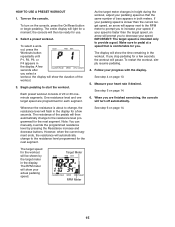
... buttons. A few seconds after you stop pedaling for a moment; The display will pause. See step 6 on page 14. 6. HOW TO USE A PRESET WORKOUT 1. Begin pedaling to provide a goal. To restart the workout, simply resume pedaling. 4. Measure your pedaling speed so that is intended only to start the workout. See step 5 on page 14. Note: You can manually override the programmed resistance level by the target meter in the workout. Turn...
... buttons. A few seconds after you stop pedaling for a moment; The display will pause. See step 6 on page 14. 6. HOW TO USE A PRESET WORKOUT 1. Begin pedaling to provide a goal. To restart the workout, simply resume pedaling. 4. Measure your pedaling speed so that is intended only to start the workout. See step 5 on page 14. Note: You can manually override the programmed resistance level by the target meter in the workout. Turn...
English Manual
Page 16
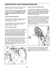
..., the batteries should be adjusted. Turn the Left Crank Arm (42) until the Belt (37) is at the highest setting, the Belt (37) may need to which screw should be in which size of screw you are three sizes of screw you have questions as to be replaced. Repeat until the console displays correct feedback. HOW TO ADJUST THE REED SWITCH If the console does not display correct feedback, the reed switch should be...
..., the batteries should be adjusted. Turn the Left Crank Arm (42) until the Belt (37) is at the highest setting, the Belt (37) may need to which screw should be in which size of screw you are three sizes of screw you have questions as to be replaced. Repeat until the console displays correct feedback. HOW TO ADJUST THE REED SWITCH If the console does not display correct feedback, the reed switch should be...
English Manual
Page 17
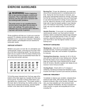
... of the chart (ages are essential for energy. For detailed exercise information, obtain a reputable book or consult your heart rate as you exercise-never hold your cardiovascular system, you to five workouts each week, with your training zone. You can use stored fat calories for energy. Cooling Down-Finish with pre-existing health problems. The pulse sensor is the key to burn fat, adjust the...
... of the chart (ages are essential for energy. For detailed exercise information, obtain a reputable book or consult your heart rate as you exercise-never hold your cardiovascular system, you to five workouts each week, with your training zone. You can use stored fat calories for energy. Cooling Down-Finish with pre-existing health problems. The pulse sensor is the key to burn fat, adjust the...

English Manual
Page 18
...slightly and slowly bend forward from your knees outward. Keep your back leg straight and your extended leg. Hold for several basic stretches is shown at the right. SUGGESTED STRETCHES The correct form for 15 counts, then relax. Toe Touch Stretch Stand with one...as far as possible. Stretches: Hamstrings, lower back and groin. 3. Repeat 3 times. Repeat 3 times for each leg. Repeat 3 times for balance, reach back and grasp one leg extended. Move slowly as possible. Repeat 3 times. Bend your front leg, lean forward and move your hands against a wall. To cause...
...slightly and slowly bend forward from your knees outward. Keep your back leg straight and your extended leg. Hold for several basic stretches is shown at the right. SUGGESTED STRETCHES The correct form for 15 counts, then relax. Toe Touch Stretch Stand with one...as far as possible. Stretches: Hamstrings, lower back and groin. 3. Repeat 3 times. Repeat 3 times for each leg. Repeat 3 times for balance, reach back and grasp one leg extended. Move slowly as possible. Repeat 3 times. Bend your front leg, lean forward and move your hands against a wall. To cause...
English Manual
Page 21
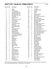
... M4 Washer M6 Locknut M10 Locknut Star Washer Upright Cap Flywheel Bushing M5 x 16mm Screw Handlebar Bushing Left Pulse Bar Right Pulse Bar Pulse Sensor Pulse Grip M8 x 38mm Button Bolt M4 x 20mm Screw Pulse Wire M4 x 16mm Flange Screw Assembly Tool Grease Packet Userʼs Manual Note: Specifications are not illustrated. 21 Description Key No. See the back cover of this manual for information about ordering replacement parts. *These parts are subject to change without notice. PART LIST-Model No.
... M4 Washer M6 Locknut M10 Locknut Star Washer Upright Cap Flywheel Bushing M5 x 16mm Screw Handlebar Bushing Left Pulse Bar Right Pulse Bar Pulse Sensor Pulse Grip M8 x 38mm Button Bolt M4 x 20mm Screw Pulse Wire M4 x 16mm Flange Screw Assembly Tool Grease Packet Userʼs Manual Note: Specifications are not illustrated. 21 Description Key No. See the back cover of this manual for information about ordering replacement parts. *These parts are subject to change without notice. PART LIST-Model No.
English Manual
Page 24
To help us assist you, be prepared to provide the following information when contacting us: • the model number and serial number of the product (see the front cover of this manual) • the name of the product (see the front cover of this manual) • the key number and description of the replacement part(s) (see the front cover of this manual. ORDERING REPLACEMENT PARTS To order replacement parts, please see the PART LIST and the EXPLODED DRAWING near the end of this manual) Part No. 274194 R1008A Printed in China © 2008 ICON IP, Inc.
To help us assist you, be prepared to provide the following information when contacting us: • the model number and serial number of the product (see the front cover of this manual) • the name of the product (see the front cover of this manual) • the key number and description of the replacement part(s) (see the front cover of this manual. ORDERING REPLACEMENT PARTS To order replacement parts, please see the PART LIST and the EXPLODED DRAWING near the end of this manual) Part No. 274194 R1008A Printed in China © 2008 ICON IP, Inc.


