
English Manual
Page 6
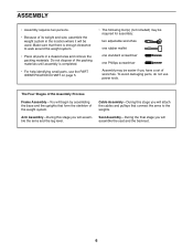
... included) may be required for assembly: two adjustable wrenches one rubber mallet one standard screwdriver one Phillips screwdriver Assembly may be easier if you will attach the cables and pulleys that connect the arms to walk around the weight system. •• Place all parts in the location where it will...
... included) may be required for assembly: two adjustable wrenches one rubber mallet one standard screwdriver one Phillips screwdriver Assembly may be easier if you will attach the cables and pulleys that connect the arms to walk around the weight system. •• Place all parts in the location where it will...

English Manual
Page 7
Do not tighten the Locknuts yet. 21 2 71 1 71 57 56 57 7 Attach the Weight Guides (21) and the Base 2 (1) to the Base (1) with two M10 x 67mm Bolts (71), two M10 Washers (57), and two M10 Locknuts (56). the Foot Plate must pivot easily. 56 1 72 38 2. Frame Assembly 1 1. Attach the Foot Plate (38) to the Stabilizer (2) with an M10 x 130mm Bolt (72) and an M10 Locknut (56). Do not overtighten the Locknut;
Do not tighten the Locknuts yet. 21 2 71 1 71 57 56 57 7 Attach the Weight Guides (21) and the Base 2 (1) to the Base (1) with two M10 x 67mm Bolts (71), two M10 Washers (57), and two M10 Locknuts (56). the Foot Plate must pivot easily. 56 1 72 38 2. Frame Assembly 1 1. Attach the Foot Plate (38) to the Stabilizer (2) with an M10 x 130mm Bolt (72) and an M10 Locknut (56). Do not overtighten the Locknut;
English Manual
Page 8
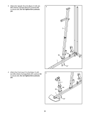
3. Attach the Front Leg (7) to the Base (1) with two M8 x 63mm Carriage Bolts (87) and two M8 4 Locknuts (58). Do not tighten the Locknuts yet. 3 4. Attach the Upright (3) to the Base (1) with two 3 M8 x 63mm Carriage Bolts (87) and two M8 Locknuts (58). Do not tighten the Locknuts yet. 58 58 1 87 7 58 58 1 87 8
3. Attach the Front Leg (7) to the Base (1) with two M8 x 63mm Carriage Bolts (87) and two M8 4 Locknuts (58). Do not tighten the Locknuts yet. 3 4. Attach the Upright (3) to the Base (1) with two 3 M8 x 63mm Carriage Bolts (87) and two M8 Locknuts (58). Do not tighten the Locknuts yet. 58 58 1 87 7 58 58 1 87 8

English Manual
Page 9
Attach the Seat Tube (6) to the Upright (3) with 5 two M8 x 65mm Bolts (68), two M8 Washers (59), and two M8 Locknuts (58). Then, slide the Weight ... Guides (21). 6 Orient nine Weights (22) so that the pin on the bottom as shown. Insert the Weight Selector (24) into the nine Weights (22). Attach the Seat Tube (6) to the Front Leg (7) in the remaining Weight (22). 5.
Attach the Seat Tube (6) to the Upright (3) with 5 two M8 x 65mm Bolts (68), two M8 Washers (59), and two M8 Locknuts (58). Then, slide the Weight ... Guides (21). 6 Orient nine Weights (22) so that the pin on the bottom as shown. Insert the Weight Selector (24) into the nine Weights (22). Attach the Seat Tube (6) to the Front Leg (7) in the remaining Weight (22). 5.

English Manual
Page 10
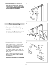
... Bumper is inserted through both sides of the Bolt Set is pointing upward. 7 60 33 69 9. Apply grease to an M10 x 64mm Bolt Set (76). 9 Attach the Leg Lever (8) to the Upright (3) with the M10 x 64mm Bolt Set (76). See steps 2 to the Front Leg (7) 8 with two M10 x 25mm Screws (74...). Attach the Leg Bumper (60) to 7. Attach the Top Frame (4) to the Weight Guides (21) with an M4 x 20mm Self-tapping Screw (69) and an M4 Washer (33). 7.
... Bumper is inserted through both sides of the Bolt Set is pointing upward. 7 60 33 69 9. Apply grease to an M10 x 64mm Bolt Set (76). 9 Attach the Leg Lever (8) to the Upright (3) with the M10 x 64mm Bolt Set (76). See steps 2 to the Front Leg (7) 8 with two M10 x 25mm Screws (74...). Attach the Leg Bumper (60) to 7. Attach the Top Frame (4) to the Weight Guides (21) with an M4 x 20mm Self-tapping Screw (69) and an M4 Washer (33). 7.
English Manual
Page 11
Attach the two Arm Pins (40) to the Pivot Frame (5) with two M10 x 25mm Button Screws (77) and...the Left Arm (10). Do not overtighten the Locknut; the Cable Pivot must pivot easily. 56 5 4 Grease 79 Arm Assembly 11 11. Attach a Handle (11) to the Top Frame (4) with the M10 x 51mm Bolt (66) and an M10 Locknut (56). Apply grease to... and an M10 Locknut (56). Apply grease to an M10 x 77mm Bolt (79). 10 Attach the Pivot Frame (5) to the Left Arm (10) with two M4 x 20mm Self-tapping Screws (69). Attach a Cable Pivot (39) to an M10 x 51mm Bolt (66). Insert the Arm Pins ...
Attach the two Arm Pins (40) to the Pivot Frame (5) with two M10 x 25mm Button Screws (77) and...the Left Arm (10). Do not overtighten the Locknut; the Cable Pivot must pivot easily. 56 5 4 Grease 79 Arm Assembly 11 11. Attach a Handle (11) to the Top Frame (4) with the M10 x 51mm Bolt (66) and an M10 Locknut (56). Apply grease to... and an M10 Locknut (56). Apply grease to an M10 x 77mm Bolt (79). 10 Attach the Pivot Frame (5) to the Left Arm (10) with two M4 x 20mm Self-tapping Screws (69). Attach a Cable Pivot (39) to an M10 x 51mm Bolt (66). Insert the Arm Pins ...

English Manual
Page 12
... Shoulder Bolt (65). Apply grease to identify the cables as you assemble them. the Left Arm must pivot easily. Attach the Right Arm (9) to two Arm Bushings (44). Do not overtighten the Locknut; Attach the Arm Cable (54) to the Pivot Frame (5) with the M8 x 22mm Shoulder Bolt (65) and an M8... Bolt 13 (67) and to the Pivot Frame (5) in the same way. 9 5 67 20 Grease 44 57 56 Grease 10 44 Cable Assembly 14 14. Attach the Left Arm (10) to the left Cable Pivot (39) with the M10 x 86mm Carriage Bolt (67), a Carriage Bolt Bushing (20), the two Arm Bushings...
... Shoulder Bolt (65). Apply grease to identify the cables as you assemble them. the Left Arm must pivot easily. Attach the Right Arm (9) to two Arm Bushings (44). Do not overtighten the Locknut; Attach the Arm Cable (54) to the Pivot Frame (5) with the M8 x 22mm Shoulder Bolt (65) and an M8... Bolt 13 (67) and to the Pivot Frame (5) in the same way. 9 5 67 20 Grease 44 57 56 Grease 10 44 Cable Assembly 14 14. Attach the Left Arm (10) to the left Cable Pivot (39) with the M10 x 86mm Carriage Bolt (67), a Carriage Bolt Bushing (20), the two Arm Bushings...
English Manual
Page 13
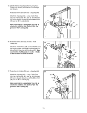
Route the Arm Cable (54) around a Thick Pulley (48). 16 Attach the Thick Pulley (48) and two Half Guards (43) to the Double U-bracket (63) with... hold the Arm Cable (54) in the groove of the V-pulley (46). 3 41 57 46 50 41 75 56 54 16. Attach the V-pulley (46), a Large Cable Trap (50), two Full Guards (41), and an M10 Washer (57) to the Upright ...Thick 15 Pulleys (not shown), and the two Thin Pulleys (not shown). Route the Arm Cable (54) over a V-pulley (46). 17 Attach the V-pulley (46), a Large Cable Trap (50), two Full Guards (41), and an M10 Washer (57) to the Upright (3) ...
Route the Arm Cable (54) around a Thick Pulley (48). 16 Attach the Thick Pulley (48) and two Half Guards (43) to the Double U-bracket (63) with... hold the Arm Cable (54) in the groove of the V-pulley (46). 3 41 57 46 50 41 75 56 54 16. Attach the V-pulley (46), a Large Cable Trap (50), two Full Guards (41), and an M10 Washer (57) to the Upright ...Thick 15 Pulleys (not shown), and the two Thin Pulleys (not shown). Route the Arm Cable (54) over a V-pulley (46). 17 Attach the V-pulley (46), a Large Cable Trap (50), two Full Guards (41), and an M10 Washer (57) to the Upright (3) ...

English Manual
Page 14
... (57), two 13mm Spacers (52), and an M10 Locknut (56). 20 56 57 52 7 48 53 52 57 71 14 Attach the Arm Cable (54) to an M8 x 22mm Shoulder Bolt (65). Attach a Thick Pulley (48) inside the Front Leg (7), above the Low Cable (53), with the M8 x 22mm Shoulder Bolt (65...
... (57), two 13mm Spacers (52), and an M10 Locknut (56). 20 56 57 52 7 48 53 52 57 71 14 Attach the Arm Cable (54) to an M8 x 22mm Shoulder Bolt (65). Attach a Thick Pulley (48) inside the Front Leg (7), above the Low Cable (53), with the M8 x 22mm Shoulder Bolt (65...

English Manual
Page 15
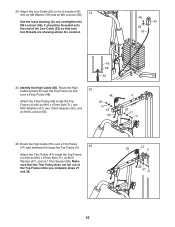
... Thick Pulley (48) and two Half Guards (43) to the Base (1) with an M10 x 46mm Bolt (81) and an M10 Locknut (56). Attach the Thick Pulley (48) and two Half Guards (43) to the Double U-bracket (63) with an M10 x 46mm Bolt (81) and an M10 Locknut (56). ... 43 53 48 1 43 81 15 Route the Low Cable (53) over a Thick 22 Pulley (48). Route the Low Cable (53) under a Thick Pulley (48). Attach the Thick Pulley (48) inside the Upright (3) with an M10 x 46mm Bolt (81) and an M10 Locknut (56). 3 56 53 48 81 22. Route the...
... Thick Pulley (48) and two Half Guards (43) to the Base (1) with an M10 x 46mm Bolt (81) and an M10 Locknut (56). Attach the Thick Pulley (48) and two Half Guards (43) to the Double U-bracket (63) with an M10 x 46mm Bolt (81) and an M10 Locknut (56). ... 43 53 48 1 43 81 15 Route the Low Cable (53) over a Thick 22 Pulley (48). Route the Low Cable (53) under a Thick Pulley (48). Attach the Thick Pulley (48) inside the Upright (3) with an M10 x 46mm Bolt (81) and an M10 Locknut (56). 3 56 53 48 81 22. Route the...
English Manual
Page 16
...Cable (55) over a Thin Pulley (47) and downward through the Top Frame (4) and 25 over a Thick Pulley (48). 48 Attach the Thick Pulley (48) inside the Top Frame (4) with an M10 x 67mm Bolt (71), an M10 Washer (57), and an...Identify the High Cable (55). Route the High Cable upward through the Top Frame (4). 26 Attach the Thin Pulley (47) inside the Top Frame (4) with an M8 Washer (59) and an M8 Locknut (58). 24.... Attach the Low Cable (53) to the U-bracket (45) 24 with an M10 x 67mm Bolt (71), two ...
...Cable (55) over a Thin Pulley (47) and downward through the Top Frame (4) and 25 over a Thick Pulley (48). 48 Attach the Thick Pulley (48) inside the Top Frame (4) with an M10 x 67mm Bolt (71), an M10 Washer (57), and an...Identify the High Cable (55). Route the High Cable upward through the Top Frame (4). 26 Attach the Thin Pulley (47) inside the Top Frame (4) with an M8 Washer (59) and an M8 Locknut (58). 24.... Attach the Low Cable (53) to the U-bracket (45) 24 with an M10 x 67mm Bolt (71), two ...

English Manual
Page 17
... (86), an M10 Washer (57), and an M10 Locknut (56). 56 43 45 55 48 51 43 66 55 47 56 4 57 86 71 29. Attach the Thick Pulley (48) inside the Top Frame (4) with the M10 x 67mm Bolt (71) used in the groove of the Thick Pulley (48) and that... the Top Frame (4). Route the High Cable (55) over a Thick Pulley 29 (48) and downward through the Top Frame (4) and over a Thin Pulley (47). 28 Attach the Thin Pulley (47) inside the Top Frame (4) with an M10 x 51mm Bolt (66) and an M10 Locknut (56). Make sure that the Small Cable...
... (86), an M10 Washer (57), and an M10 Locknut (56). 56 43 45 55 48 51 43 66 55 47 56 4 57 86 71 29. Attach the Thick Pulley (48) inside the Top Frame (4) with the M10 x 67mm Bolt (71) used in the groove of the Thick Pulley (48) and that... the Top Frame (4). Route the High Cable (55) over a Thick Pulley 29 (48) and downward through the Top Frame (4) and over a Thin Pulley (47). 28 Attach the Thin Pulley (47) inside the Top Frame (4) with an M10 x 51mm Bolt (66) and an M10 Locknut (56). Make sure that the Small Cable...

English Manual
Page 18
... Frame. 91 61 62 82 64 3 32. Tighten the M12 Nut (84) against the Large Washer (85). 55 84 85 24 Seat Assembly 31 31. Attach the Seat (15) to the Backrest Frame (61) with two M6 x 16mm Screws (62), an M6 x 38mm 32 Screw (95), and an M6 Washer (82... Seat Frame. Wide End 73 9852 91 95 62 6 18 Tighten the High Cable (55) into the Upright and one of the Weight Selector (24). Attach the Backrest (16) to the Seat Frame (73) with two M6 x 16mm Screws (62), an M6 x 32mm Screw (64), and an M6 Washer (82). 16...
... Frame. 91 61 62 82 64 3 32. Tighten the M12 Nut (84) against the Large Washer (85). 55 84 85 24 Seat Assembly 31 31. Attach the Seat (15) to the Backrest Frame (61) with two M6 x 16mm Screws (62), an M6 x 38mm 32 Screw (95), and an M6 Washer (82... Seat Frame. Wide End 73 9852 91 95 62 6 18 Tighten the High Cable (55) into the Upright and one of the Weight Selector (24). Attach the Backrest (16) to the Seat Frame (73) with two M6 x 16mm Screws (62), an M6 x 32mm Screw (64), and an M6 Washer (82). 16...

English Manual
Page 19
... Pad (28) onto each Small Foam Pad. 33 34 28 7 34 28 8 29 28 28 34 34 34. Then, attach a Shroud Clamp (90) to the left side of the Pad Tube (29). Attach a Shroud Support (19) and the top of the 34 Left Shroud (17) to the top of the Leg Lever...
... Pad (28) onto each Small Foam Pad. 33 34 28 7 34 28 8 29 28 28 34 34 34. Then, attach a Shroud Clamp (90) to the left side of the Pad Tube (29). Attach a Shroud Support (19) and the top of the 34 Left Shroud (17) to the top of the Leg Lever...

English Manual
Page 20
Attach a Shroud Support (19) and the bottom of the Left Shroud (17) to the Base (1) and the 35 Stabilizer (2) ...need to the Curl Post (13) 36 with four M4.2 x 16mm Self-tapping Screws (49) and four M4 Washers (33). Attach the Curl Pad (14) to remove the slack by tightening the cables. Tighten the M4.2 x 16mm Self-tapping Screws (49) and...make sure that all parts have been properly tightened. Before using the weight system, pull each cable a few times to attach the Right Shroud (not shown). 35. See the CABLE DIAGRAM on page 25. 20 See MAINTENANCE on page 24 for ...
Attach a Shroud Support (19) and the bottom of the Left Shroud (17) to the Base (1) and the 35 Stabilizer (2) ...need to the Curl Post (13) 36 with four M4.2 x 16mm Self-tapping Screws (49) and four M4 Washers (33). Attach the Curl Pad (14) to remove the slack by tightening the cables. Tighten the M4.2 x 16mm Self-tapping Screws (49) and...make sure that all parts have been properly tightened. Before using the weight system, pull each cable a few times to attach the Right Shroud (not shown). 35. See the CABLE DIAGRAM on page 25. 20 See MAINTENANCE on page 24 for ...

English Manual
Page 21
... each exercise station may vary from your exercise program. Make sure that all parts are properly tightened each weight station. 22 26 ATTACHING THE ACCESSORIES Attach the Lat Bar (35) to the High Cable (55) at each time the weight system is in the correct starting position for the ...to get the most benefit from the weight setting. Also, refer to the accompanying exercise guide to adjust the weight system. For some exercises, attach the Chain (83) between the Lat Bar and the High Cable so that the bent end touches the weight stack. ADJUSTMENT This section explains how...
... each exercise station may vary from your exercise program. Make sure that all parts are properly tightened each weight station. 22 26 ATTACHING THE ACCESSORIES Attach the Lat Bar (35) to the High Cable (55) at each time the weight system is in the correct starting position for the ...to get the most benefit from the weight setting. Also, refer to the accompanying exercise guide to adjust the weight system. For some exercises, attach the Chain (83) between the Lat Bar and the High Cable so that the bent end touches the weight stack. ADJUSTMENT This section explains how...

