
English Manual
Page 1
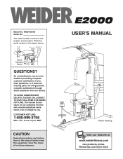
... precautions and instructions in this manual before using this manual for future reference. ¨ USERÕS MANUAL Patent Pending Visit our website at www.weiderfitness.com new products, prizes, fitness tips, and much more! The trained technicians on our customer hot line will guarantee complete satisfaction through direct assistance from our factory. As a manufacturer, we are missing parts, we will...
... precautions and instructions in this manual before using this manual for future reference. ¨ USERÕS MANUAL Patent Pending Visit our website at www.weiderfitness.com new products, prizes, fitness tips, and much more! The trained technicians on our customer hot line will guarantee complete satisfaction through direct assistance from our factory. As a manufacturer, we are missing parts, we will...
English Manual
Page 2
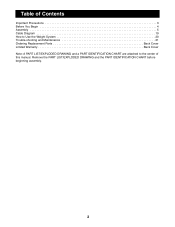
Remove the PART LIST/EXPLODED DRAWING and the PART IDENTIFICATION CHART before beginning assembly. 2 Table of Contents Important Precautions 3 Before You Begin 4 Assembly 5 Cable Diagram 19 How to Use the Weight System 20 Trouble-shooting and Maintenance 21 Ordering Replacement Parts Back Cover Limited Warranty Back Cover Note: A PART LIST/EXPLODED DRAWING and a PART IDENTIFICATION CHART are attached to the center of this manual.
Remove the PART LIST/EXPLODED DRAWING and the PART IDENTIFICATION CHART before beginning assembly. 2 Table of Contents Important Precautions 3 Before You Begin 4 Assembly 5 Cable Diagram 19 How to Use the Weight System 20 Trouble-shooting and Maintenance 21 Ordering Replacement Parts Back Cover Limited Warranty Back Cover Note: A PART LIST/EXPLODED DRAWING and a PART IDENTIFICATION CHART are attached to the center of this manual.
English Manual
Page 3
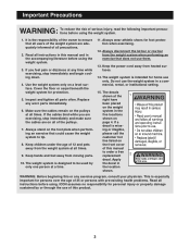
... order a free replacement 2 decal. The weight system is especially important for home use them. 13. If a decal is the responsibility of the owner to tip. 8. Keep children under the age of all users of the weight system are on page 4. Always disconnect the lat bar or row bar from the weight system at a time. 11. It is miss- Replace any time while exercising, stop immediately...
... order a free replacement 2 decal. The weight system is especially important for home use them. 13. If a decal is the responsibility of the owner to tip. 8. Keep children under the age of all users of the weight system are on page 4. Always disconnect the lat bar or row bar from the weight system at a time. 11. It is miss- Replace any time while exercising, stop immediately...
English Manual
Page 4
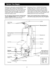
... Service Please use the drawing below to familiarize yourself with the major parts and how they fit together. High Pulley Station Lat Bar Warning Decal 2 Warning Decal 1 Ab Pulley Station Curl Pad Console Warning Decal 2 Leg Lever Low Pulley Station Row Bar Foot Plate 4 Butterfly Arm Backrest Press Arm Shroud Seat Warning Decal 2 (on a decal attached to achieve the results you , please note the product model number and serial number before using...
... Service Please use the drawing below to familiarize yourself with the major parts and how they fit together. High Pulley Station Lat Bar Warning Decal 2 Warning Decal 1 Ab Pulley Station Curl Pad Console Warning Decal 2 Leg Lever Low Pulley Station Row Bar Foot Plate 4 Butterfly Arm Backrest Press Arm Shroud Seat Warning Decal 2 (on a decal attached to achieve the results you , please note the product model number and serial number before using...
English Manual
Page 5
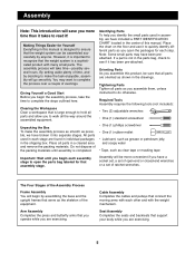
...Start Before you assemble them, unless instructed to hold all parts and allow you identify the small parts used in the drawings. All parts used in assembly, we have broken it into separate stages. Cable Assembly Completes the cables and pulleys that support your body while you are oriented as you begin the assembly... if you have a socket set, a set of open-end or closed-end wrenches or a set of ratchet wrenches. Seat Assembly Completes the seats and backrests that connect the moving arms with each assembly stage to open the parts bag labeled for Yourself Everything in...
...Start Before you assemble them, unless instructed to hold all parts and allow you identify the small parts used in the drawings. All parts used in assembly, we have broken it into separate stages. Cable Assembly Completes the cables and pulleys that support your body while you are oriented as you begin the assembly... if you have a socket set, a set of open-end or closed-end wrenches or a set of ratchet wrenches. Seat Assembly Completes the seats and backrests that connect the moving arms with each assembly stage to open the parts bag labeled for Yourself Everything in...
English Manual
Page 6
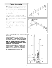
Open the parts bag labeled ÒFRAME ASSEMBLY.Ó Press a 2Ó Square Outer Cap (51) onto each end of the Base (8). Insert two 5/16Ó x 2 1/2Ó Carriage Bolts (52) up through the Base (8). Make sure the Rear Upright (18) is oriented as shown. Press a 2Ó Square Inner Cap (21) into the top of the Bracket 53 5 53 14 8 52...
Open the parts bag labeled ÒFRAME ASSEMBLY.Ó Press a 2Ó Square Outer Cap (51) onto each end of the Base (8). Insert two 5/16Ó x 2 1/2Ó Carriage Bolts (52) up through the Base (8). Make sure the Rear Upright (18) is oriented as shown. Press a 2Ó Square Inner Cap (21) into the top of the Bracket 53 5 53 14 8 52...
English Manual
Page 8
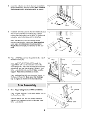
... Support Plate (27) is angled as shown. Press the Angle Cap (62) onto the end of the wire bundle. 8. Make sure that some slack is attached exactly as shown. 26 83 Wires 9. Lubricate the 3/8Ó x 8Ó Bolt (59). Attach the indicated end of the Console Cord (83) to 8 the indicated end of the rod on the Seat Frame (36) over the Wire...
... Support Plate (27) is angled as shown. Press the Angle Cap (62) onto the end of the wire bundle. 8. Make sure that some slack is attached exactly as shown. 26 83 Wires 9. Lubricate the 3/8Ó x 8Ó Bolt (59). Attach the indicated end of the Console Cord (83) to 8 the indicated end of the rod on the Seat Frame (36) over the Wire...
English Manual
Page 10
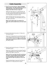
Open the parts bag labeled ÒCABLE ASSEMBLY AND PULLEYS.Ó For Cable identification and routing during steps 15Ð30, refer to the Cable Diagram and Cable ID Chart on the cable. It may be helpful to take the Butterfly Arm (47) through one full range of motion to the Top Frame (1) with a 3/8Ó x 2 1/4Ó Bolt (65) and a 3/8Ó Nylon Locknut (57). Route the High Cable (2) under...
Open the parts bag labeled ÒCABLE ASSEMBLY AND PULLEYS.Ó For Cable identification and routing during steps 15Ð30, refer to the Cable Diagram and Cable ID Chart on the cable. It may be helpful to take the Butterfly Arm (47) through one full range of motion to the Top Frame (1) with a 3/8Ó x 2 1/4Ó Bolt (65) and a 3/8Ó Nylon Locknut (57). Route the High Cable (2) under...
English Manual
Page 11
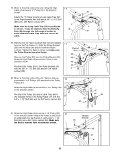
.... Attach the ÒVÓ-Pulley (6) and a Long Cable Trap (50) to the Pulley Plates (31). Wrap the High Cable (2) around a ÒVÓ-Pulley (6) in the direction shown. Make sure 60 the Bolt is positioned as shown. Remove the pre- 20 assembled 3 1/2Ó Pulleys (35) attached to the Right Butterfly Arm (48) with the 3/8Ó x 1 1/2Ó Bolt (60) and the 3/8Ó Nylon 2 Jamnut (63). 20. Move...
.... Attach the ÒVÓ-Pulley (6) and a Long Cable Trap (50) to the Pulley Plates (31). Wrap the High Cable (2) around a ÒVÓ-Pulley (6) in the direction shown. Make sure 60 the Bolt is positioned as shown. Remove the pre- 20 assembled 3 1/2Ó Pulleys (35) attached to the Right Butterfly Arm (48) with the 3/8Ó x 1 1/2Ó Bolt (60) and the 3/8Ó Nylon 2 Jamnut (63). 20. Move...
English Manual
Page 12
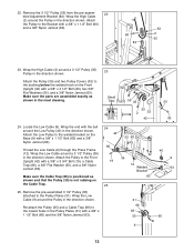
Wrap the Low Cable around a 3 1/2Ó Pulley (35) in the direction shown. Remove the pre-assembled 3 1/2Ó Pulley (35) attached to the Front Upright (42) with a 3/8Ó x 1 1/2Ó Bolt (60) and the ...Bolt (19), a Cable Trap (66), a 3/8Ó Flat Washer (55), and a 3/8Ó Nylon Jamnut (63). Attach the Pulley (35) and two Pulley Covers (32) to the lowest holes in the direction shown. Make sure the parts are assembled exactly as shown and that the Pulley (35) is not rubbing on the Cable Trap. 25. Locate the Low Cable (9). Re-attach the Pulley (35) and a Cable...
Wrap the Low Cable around a 3 1/2Ó Pulley (35) in the direction shown. Remove the pre-assembled 3 1/2Ó Pulley (35) attached to the Front Upright (42) with a 3/8Ó x 1 1/2Ó Bolt (60) and the ...Bolt (19), a Cable Trap (66), a 3/8Ó Flat Washer (55), and a 3/8Ó Nylon Jamnut (63). Attach the Pulley (35) and two Pulley Covers (32) to the lowest holes in the direction shown. Make sure the parts are assembled exactly as shown and that the Pulley (35) is not rubbing on the Cable Trap. 25. Locate the Low Cable (9). Re-attach the Pulley (35) and a Cable...
English Manual
Page 14
... Wrap the Low Cable (9) around a 3 1/2Ó Pulley (35) in the parts bag labeled ÒSEAT ASSEMBLY.Ó 12 Seat Assembly 31 9 73 44 31. Insert the 1/4Ó x 2Ó Carriage Bolt (38) into the indicated hole in the Seat Plate (37). Tighten a 1/4Ó Nylon Locknut (89) with a Cable Clip (73). Attach the Seat Plate to the Seat Frame (36) with two 1/4Ó x 2 1/2Ó Screws (43) and...
... Wrap the Low Cable (9) around a 3 1/2Ó Pulley (35) in the parts bag labeled ÒSEAT ASSEMBLY.Ó 12 Seat Assembly 31 9 73 44 31. Insert the 1/4Ó x 2Ó Carriage Bolt (38) into the indicated hole in the Seat Plate (37). Tighten a 1/4Ó Nylon Locknut (89) with a Cable Clip (73). Attach the Seat Plate to the Seat Frame (36) with two 1/4Ó x 2 1/2Ó Screws (43) and...
English Manual
Page 15
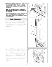
...the Leg Lever (29) can be turned freely after the Curl Post (10) is attached in step 39, the Console Cord (83) should be pressed between the Seat Frame and the bracket on the Leg lever (29). Secure the Curl Post with four #8 x 1/2Ó Screws ...Attach the Console Upright (94) to the Curl Post (10) with two 1/4Ó x 5/8Ó Screws (95). Press two 3/4Ó Round Inner Caps (34) into each of the welded brackets is between the bottom of the Console Cord (83) into the Console Base (61). Attach the Console (39) to the the Console Upright (94) with the 5/16Ó x 2Ó Knob...
...the Leg Lever (29) can be turned freely after the Curl Post (10) is attached in step 39, the Console Cord (83) should be pressed between the Seat Frame and the bracket on the Leg lever (29). Secure the Curl Post with four #8 x 1/2Ó Screws ...Attach the Console Upright (94) to the Curl Post (10) with two 1/4Ó x 5/8Ó Screws (95). Press two 3/4Ó Round Inner Caps (34) into each of the welded brackets is between the bottom of the Console Cord (83) into the Console Base (61). Attach the Console (39) to the the Console Upright (94) with the 5/16Ó x 2Ó Knob...
English Manual
Page 16
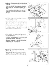
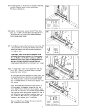
..., it can occur. 83 Wires Lubricate 26 Brass Piece 26 38c.To adjust the Weight Mechanism (26), begin with the 38c ÒUÓ-bracket found on how to the indicated screw. 38b.Check the brass piece that is pictured at the right. See page 20 for instructions on one end of the Power Adapter Cord (64) into an outlet...
..., it can occur. 83 Wires Lubricate 26 Brass Piece 26 38c.To adjust the Weight Mechanism (26), begin with the 38c ÒUÓ-bracket found on how to the indicated screw. 38b.Check the brass piece that is pictured at the right. See page 20 for instructions on one end of the Power Adapter Cord (64) into an outlet...
English Manual
Page 17
...an exercise is started and the time resistance is pictured in the inset 38d drawing. When the lowest setting is too tight, the Weight Mechan- Check the brass piece that is felt. Continue to decrease the resistance until the brass piece is at its lowest weight ...lapse between the brass piece and the Weight Mechanism (26) after each adjustment until the console is barely touching the shaded area on the console. If the motor stalls or hesitates, loosen the 3/8Ó Tap Screw (86) 1/4 turn . Disconnect the Power Adapter Cord (connected in step 37) from side to side. 85 ...
...an exercise is started and the time resistance is pictured in the inset 38d drawing. When the lowest setting is too tight, the Weight Mechan- Check the brass piece that is felt. Continue to decrease the resistance until the brass piece is at its lowest weight ...lapse between the brass piece and the Weight Mechanism (26) after each adjustment until the console is barely touching the shaded area on the console. If the motor stalls or hesitates, loosen the 3/8Ó Tap Screw (86) 1/4 turn . Disconnect the Power Adapter Cord (connected in step 37) from side to side. 85 ...
English Manual
Page 18
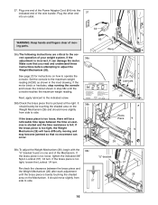
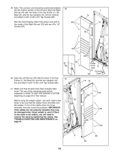
... is used. Note: The console cord should be sure that all parts have been properly tightened. If one of this manual. Align the Right Shroud (79) with the holes in the Top Frame (1), the Base (8), and the two Uprights (18, 42 [not shown]) and attach it with 14 #8 x 3/4Ó Tap Screws (80). Attach the power cord jack to remove the slack by tightening the cables...
... is used. Note: The console cord should be sure that all parts have been properly tightened. If one of this manual. Align the Right Shroud (79) with the holes in the Top Frame (1), the Base (8), and the two Uprights (18, 42 [not shown]) and attach it with 14 #8 x 3/4Ó Tap Screws (80). Attach the power cord jack to remove the slack by tightening the cables...
English Manual
Page 20
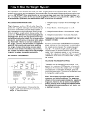
...; (minimum weight). The resistance shown on the press arm, butterfly arms, or leg lever while adjusting the weight. If at minimum or maximum weight for each part of 1 pound. Weight Increase ButtonÑIncreases the weight. If there is any time during console adjustment the motor binds or hesitates, stop running the console and refer to steps 38a to 38g on the power when using the weight system, always unplug the power cord. Do...
...; (minimum weight). The resistance shown on the press arm, butterfly arms, or leg lever while adjusting the weight. If at minimum or maximum weight for each part of 1 pound. Weight Increase ButtonÑIncreases the weight. If there is any time during console adjustment the motor binds or hesitates, stop running the console and refer to steps 38a to 38g on the power when using the weight system, always unplug the power cord. Do...

English Manual
Page 21
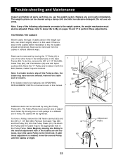
ATTACHING THE LAT BAR, ROW BAR, AB STRAP OR HANDLE TO THE LOW, HIGH OR AB PULLEY STATION Attach the Lat Bar (76) to the Low Cable (9) with the 5/16Ó x 2Ó Knob (72). Use the same method for the exercise to the high pulley station or the ab station...Cable Clip (73). The Row Bar (70), Handle (75) or Ab Strap (81) can be attached in the correct starting position for attaching any of the attachments to be performed. Adjust the length of the Chain between the Lat Bar and the Cable so the Lat Bar is between the Seat Frame and the bracket on the Leg lever (29). To remove...
ATTACHING THE LAT BAR, ROW BAR, AB STRAP OR HANDLE TO THE LOW, HIGH OR AB PULLEY STATION Attach the Lat Bar (76) to the Low Cable (9) with the 5/16Ó x 2Ó Knob (72). Use the same method for the exercise to the high pulley station or the ab station...Cable Clip (73). The Row Bar (70), Handle (75) or Ab Strap (81) can be attached in the correct starting position for attaching any of the attachments to be performed. Adjust the length of the Chain between the Lat Bar and the Cable so the Lat Bar is between the Seat Frame and the bracket on the Leg lever (29). To remove...
English Manual
Page 22
... Cables need to the second adjustment hole. Re-attach the Pulley and the Cable Trap to the weight system, the weight mechanism must also be cleaned using the Pulley Plates (31). If additional adjustment is felt, the Cables should be replaced, see ORDERING REPLACEMENT PARTS on the weight system, can be removed by moving one Pulley to be tightened. Trouble-shooting and Maintenance Inspect and tighten all parts each time you use solvents. Do not use...
... Cables need to the second adjustment hole. Re-attach the Pulley and the Cable Trap to the weight system, the weight mechanism must also be cleaned using the Pulley Plates (31). If additional adjustment is felt, the Cables should be replaced, see ORDERING REPLACEMENT PARTS on the weight system, can be removed by moving one Pulley to be tightened. Trouble-shooting and Maintenance Inspect and tighten all parts each time you use solvents. Do not use...
English Manual
Page 26
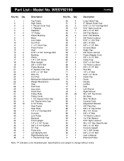
... Lat Bar Grip Left Shroud Right Shroud #8 x 3/4Ó Tap Screw Ab Strap Wire Tie Block Console Cord Adjustment Bracket 3/8Ó Plain Nut 3/8Ó x 4Ó Tap Screw #8 x 1/2Ó Screw 3/8Ó x 3Ó Bolt 1/4Ó Nylon Locknut 1/4Ó Flat Washer 5/16Ó Nylon Jamnut #8 x 1/2Ó Hex Head Screw 3/8Ó x 4 1/2Ó Bolt Console Upright 1/4Ó x 5/8Ó Screw 3/8Ó x 2 1/2Ó Bolt UserÕs Manual Exercise Poster Note: Ò#Ó indicates a non-illustrated part. WESY92190 R1299A Key No. Part List...
... Lat Bar Grip Left Shroud Right Shroud #8 x 3/4Ó Tap Screw Ab Strap Wire Tie Block Console Cord Adjustment Bracket 3/8Ó Plain Nut 3/8Ó x 4Ó Tap Screw #8 x 1/2Ó Screw 3/8Ó x 3Ó Bolt 1/4Ó Nylon Locknut 1/4Ó Flat Washer 5/16Ó Nylon Jamnut #8 x 1/2Ó Hex Head Screw 3/8Ó x 4 1/2Ó Bolt Console Upright 1/4Ó x 5/8Ó Screw 3/8Ó x 2 1/2Ó Bolt UserÕs Manual Exercise Poster Note: Ò#Ó indicates a non-illustrated part. WESY92190 R1299A Key No. Part List...
English Manual
Page 28
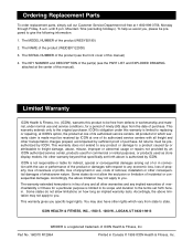
... us assist you . The SERIAL NUMBER of the product (see the PART LIST and EXPLODED DRAWING attached at one of ICON Health & Fitness, Inc. All returns must be received by an ICON authorized service center, products used for commercial or rental purposes, or products used as store display models. Some states do not allow limitations on how long an implied warranty lasts. Part No. 160370 R1299A Printed...
... us assist you . The SERIAL NUMBER of the product (see the PART LIST and EXPLODED DRAWING attached at one of ICON Health & Fitness, Inc. All returns must be received by an ICON authorized service center, products used for commercial or rental purposes, or products used as store display models. Some states do not allow limitations on how long an implied warranty lasts. Part No. 160370 R1299A Printed...


