

English Manual
Page 1
... product (see the limited warranty on the back cover of this manual for future reference. please contact Customer Care. CALL TOLL-FREE: 1-877-992-5999 Mon.-Fri. 6 a.m.-6 p.m. www.weiderfitness.com Model No. If you have questions, or if parts are damaged or missing, DO NOT CONTACT THE STORE; Keep this manual) before using this equipment. USERʼS MANUAL WEBE1998.1 Serial No. MT...
... product (see the limited warranty on the back cover of this manual for future reference. please contact Customer Care. CALL TOLL-FREE: 1-877-992-5999 Mon.-Fri. 6 a.m.-6 p.m. www.weiderfitness.com Model No. If you have questions, or if parts are damaged or missing, DO NOT CONTACT THE STORE; Keep this manual) before using this equipment. USERʼS MANUAL WEBE1998.1 Serial No. MT...
English Manual
Page 2
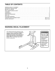
Apply the decal in the location shown. Note: The decal(s) may not be shown at actual size. 2 TABLE OF CONTENTS WARNING DECAL PLACEMENT 2 IMPORTANT PRECAUTIONS 3 BEFORE YOU BEGIN 4 PART IDENTIFICATION CHART 5 ASSEMBLY 6 ADJUSTMENT 11 EXERCISE GUIDELINES 12 PART LIST 14 EXPLODED DRAWING 15 ORDERING REPLACEMENT PARTS Back Cover LIMITED WARRANTY Back Cover WARNING DECAL PLACEMENT This drawing shows the location(s) of this manual and request a free replacement decal. If a decal is missing or illegible, see the front cover of the warning decal(s).
Apply the decal in the location shown. Note: The decal(s) may not be shown at actual size. 2 TABLE OF CONTENTS WARNING DECAL PLACEMENT 2 IMPORTANT PRECAUTIONS 3 BEFORE YOU BEGIN 4 PART IDENTIFICATION CHART 5 ASSEMBLY 6 ADJUSTMENT 11 EXERCISE GUIDELINES 12 PART LIST 14 EXPLODED DRAWING 15 ORDERING REPLACEMENT PARTS Back Cover LIMITED WARRANTY Back Cover WARNING DECAL PLACEMENT This drawing shows the location(s) of this manual and request a free replacement decal. If a decal is missing or illegible, see the front cover of the warning decal(s).

English Manual
Page 3
... resistance with weights. Do not use of this manual and all warnings on your physician. Replace any exercise program, consult your exercise tower. IMPORTANT PRECAUTIONS WARNING: To reduce the risk of serious injury, read all important precautions and instructions in a commercial, rental, or institutional setting. 4. Before beginning any worn parts immediately. 11. Your exercise tower is the responsibility of the owner to be used with the exercise tower...
... resistance with weights. Do not use of this manual and all warnings on your physician. Replace any exercise program, consult your exercise tower. IMPORTANT PRECAUTIONS WARNING: To reduce the risk of serious injury, read all important precautions and instructions in a commercial, rental, or institutional setting. 4. Before beginning any worn parts immediately. 11. Your exercise tower is the responsibility of the owner to be used with the exercise tower...
English Manual
Page 4
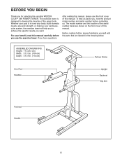
...) Pull-up Frame Arm Pad Handles Upright Backrest Dip Arm Footrest Handle 4 ASSEMBLED DIMENSIONS: Height: 7 ft. (213 cm) Width: 3 ft. 5 in. (104 cm) Depth: 3 ft. 8 in the drawing below. To help you want. If you , note the product model number and serial number before you for selecting the versatile WEIDER CLUB™ 290 POWER TOWER. For your cardiovascular system, the exercise tower will help us assist...
...) Pull-up Frame Arm Pad Handles Upright Backrest Dip Arm Footrest Handle 4 ASSEMBLED DIMENSIONS: Height: 7 ft. (213 cm) Width: 3 ft. 5 in. (104 cm) Depth: 3 ft. 8 in the drawing below. To help you want. If you , note the product model number and serial number before you for selecting the versatile WEIDER CLUB™ 290 POWER TOWER. For your cardiovascular system, the exercise tower will help us assist...
English Manual
Page 5
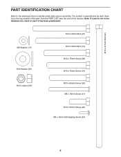
PART IDENTIFICATION CHART Refer to the drawings below to see if it has been preattached. M10 x 215mm Bolt (22) M6 Washer (15) M10 Washer (30) M10 Locknut (25) M10 x 95mm Bolt (27) M10 x 90mm Bolt (19) M10 x 75mm Screw (36) M10 x 70mm Screw (31) M10 x 65mm Screw (29) M6 x 70mm Screw (21) M10 x 30mm Screw (20) M4 x 16mm Self-tapping Screw (24) 5 Note: If a part is not in the hardware kit, check to identify small parts used in parentheses by each drawing is the key number of the part, from the PART LIST near the end of this manual. The number in assembly.
PART IDENTIFICATION CHART Refer to the drawings below to see if it has been preattached. M10 x 215mm Bolt (22) M6 Washer (15) M10 Washer (30) M10 Locknut (25) M10 x 95mm Bolt (27) M10 x 90mm Bolt (19) M10 x 75mm Screw (36) M10 x 70mm Screw (31) M10 x 65mm Screw (29) M6 x 70mm Screw (21) M10 x 30mm Screw (20) M4 x 16mm Self-tapping Screw (24) 5 Note: If a part is not in the hardware kit, check to identify small parts used in parentheses by each drawing is the key number of the part, from the PART LIST near the end of this manual. The number in assembly.
English Manual
Page 6
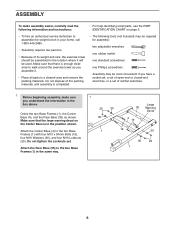
... you have a socket set, a set of open-end or closed-end wrenches, or a set of its weight and size, the exercise tower should be used. Attach the Rear Base (35) to the two Base Frames (1) with four M10 x 90mm Bolts (19), four M10 Washers (30), and four M10 Locknuts (25). ASSEMBLY To make sure you assemble it will be assembled in the location where it . •...
... you have a socket set, a set of open-end or closed-end wrenches, or a set of its weight and size, the exercise tower should be used. Attach the Rear Base (35) to the two Base Frames (1) with four M10 x 90mm Bolts (19), four M10 Washers (30), and four M10 Locknuts (25). ASSEMBLY To make sure you assemble it will be assembled in the location where it . •...
English Manual
Page 7
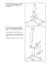
2. Do not tighten the Locknuts yet. 2 25 27 4 3. See steps 1-3. Insert the Upright (3) into the Upright Base (2). Do not tighten the Locknuts yet. Attach the Support (5) to the Rear Base (35) 3 with two M10 x 95mm Bolts (27) and two 2 M10 Locknuts (25). Attach the Upright Base (2) to the 3 Upright Base (2) with four M10 x 30mm Screws (20). Tighten the M10 Locknuts (25). 20 5 20 19 2 25 35 7 Attach the Upright (3) and the Support (5) to the Center Base (4) with two M10 x 90mm Bolts (19) and two M10 Locknuts (25).
2. Do not tighten the Locknuts yet. 2 25 27 4 3. See steps 1-3. Insert the Upright (3) into the Upright Base (2). Do not tighten the Locknuts yet. Attach the Support (5) to the Rear Base (35) 3 with two M10 x 95mm Bolts (27) and two 2 M10 Locknuts (25). Attach the Upright Base (2) to the 3 Upright Base (2) with four M10 x 30mm Screws (20). Tighten the M10 Locknuts (25). 20 5 20 19 2 25 35 7 Attach the Upright (3) and the Support (5) to the Center Base (4) with two M10 x 90mm Bolts (19) and two M10 Locknuts (25).

English Manual
Page 8
... (25). Do not tighten the Screw yet. Attach the Right Handle (8) to the Upright (3) with an M10 x 75mm Screw (36) and an M10 Washer (30). Attach the Left Pull-up Arm (34) with an M10 x 65mm Screw (29), an 4 M10 x 70mm Screw (31), and two M10 Washers (30). 7 Press a 50mm Round Inner Cap (12) into the Upright (3). 5 Attach the Left Pull-up...
... (25). Do not tighten the Screw yet. Attach the Right Handle (8) to the Upright (3) with an M10 x 75mm Screw (36) and an M10 Washer (30). Attach the Left Pull-up Arm (34) with an M10 x 65mm Screw (29), an 4 M10 x 70mm Screw (31), and two M10 Washers (30). 7 Press a 50mm Round Inner Cap (12) into the Upright (3). 5 Attach the Left Pull-up...

English Manual
Page 9
...) with an M4 x 16mm Self-tapping Screw (24). Apply some of the included grease to the Upright (3) with the M10 x 215mm Bolt (22) and an M10 Locknut (25). Attach the tether on the Pin (23) to the Upright (3) with two M10 x 65mm Screws (29), two M10 Washers (30), and two M10 Locknuts (25). 29 6... 33 30 25 7. the Dip Arms must pivot easily. Attach the ...
...) with an M4 x 16mm Self-tapping Screw (24). Apply some of the included grease to the Upright (3) with the M10 x 215mm Bolt (22) and an M10 Locknut (25). Attach the tether on the Pin (23) to the Upright (3) with two M10 x 65mm Screws (29), two M10 Washers (30), and two M10 Locknuts (25). 29 6... 33 30 25 7. the Dip Arms must pivot easily. Attach the ...
English Manual
Page 10
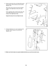
... the Right Dip Arm (6). Press a Bushing (18), the Short Foam Grip (16), and a 28mm Round Inner Cap (14) onto the handle on the Right Dip Arm (6) with two M6 x 70mm Screws (21) and two M6 Washers (15). Make sure that all parts are properly tightened before you use the exercise tower. 10 8. Attach an Arm Pad (10) to the Upright (3) with 9 two...
... the Right Dip Arm (6). Press a Bushing (18), the Short Foam Grip (16), and a 28mm Round Inner Cap (14) onto the handle on the Right Dip Arm (6) with two M6 x 70mm Screws (21) and two M6 Washers (15). Make sure that all parts are properly tightened before you use the exercise tower. 10 8. Attach an Arm Pad (10) to the Upright (3) with 9 two...

English Manual
Page 11
... accompanying exercise guide to see the correct form for important information about how to the up position, as shown in the down position, first remove the Pin (23). The exercise tower can be behind the Upright when the Dip Arms are in the up or down position. 3 6 33 23 11 do not use solvents. Then, move the Dip Arms (6, 33) to adjust the exercise tower. The Pin...
... accompanying exercise guide to see the correct form for important information about how to the up position, as shown in the down position, first remove the Pin (23). The exercise tower can be behind the Upright when the Dip Arms are in the up or down position. 3 6 33 23 11 do not use solvents. Then, move the Dip Arms (6, 33) to adjust the exercise tower. The Pin...
English Manual
Page 12
... pace and be sensitive to your weight and key body measurements once a month. To give your workouts, vary the exercises from workout to regenerate. Cross Training-Combine strength training and aerobic exercise by using high amounts of resistance. WORKOUT GUIDELINES Familiarize yourself with 3 sets of 8 repetitions for each exercise you want to determine the appropriate length of time for each EXERCISE FORM Move through the full range of...
... pace and be sensitive to your weight and key body measurements once a month. To give your workouts, vary the exercises from workout to regenerate. Cross Training-Combine strength training and aerobic exercise by using high amounts of resistance. WORKOUT GUIDELINES Familiarize yourself with 3 sets of 8 repetitions for each exercise you want to determine the appropriate length of time for each EXERCISE FORM Move through the full range of...

English Manual
Page 13
Sets Reps Exercise 6. Sets Reps 2. 7. 3. 8. 4. 9. 5. 10. Sets Reps Exercise 6. 7. 8. 9. 10. Sets Reps Time Distance Speed Strength Date: Aerobic Date: Exercise 1. 2. 3. 4. 5. Lbs. Lbs. Sets Reps Time Distance Speed 13 EXERCISE LOG Make copies of this page, and use the copies to make exercise a regular and enjoyable part of your strength and aerobic workouts. Exercise Lbs. Lbs. Sets Reps Exercise 6. 7. 8. 9. 10. Aerobic Date: Exercise Time Distance Speed Strength Date: Aerobic Date: Exercise 1. 2. 3. 4. 5. Strength Date: Exercise 1. Lbs. Exercise...
Sets Reps Exercise 6. Sets Reps 2. 7. 3. 8. 4. 9. 5. 10. Sets Reps Exercise 6. 7. 8. 9. 10. Sets Reps Time Distance Speed Strength Date: Aerobic Date: Exercise 1. 2. 3. 4. 5. Lbs. Lbs. Sets Reps Time Distance Speed 13 EXERCISE LOG Make copies of this page, and use the copies to make exercise a regular and enjoyable part of your strength and aerobic workouts. Exercise Lbs. Lbs. Sets Reps Exercise 6. 7. 8. 9. 10. Aerobic Date: Exercise Time Distance Speed Strength Date: Aerobic Date: Exercise 1. 2. 3. 4. 5. Strength Date: Exercise 1. Lbs. Exercise...

English Manual
Page 14
... Screw 30 18 M10 Washer 31 4 M10 x 70mm Screw 32 1 Grip Tape 33 1 Left Dip Arm 34 1 Left Pull-up Arm 35 1 Rear Base 36 2 M10 x 75mm Screw 37 2 50mm x 70mm Inner Cap * - Grease Packet Note: Specifications are not illustrated. 14 Description Key No. Userʼs Manual * - PART LIST-Model No. For information about ordering replacement parts, see the back cover of this manual. *These parts are subject to change without...
... Screw 30 18 M10 Washer 31 4 M10 x 70mm Screw 32 1 Grip Tape 33 1 Left Dip Arm 34 1 Left Pull-up Arm 35 1 Rear Base 36 2 M10 x 75mm Screw 37 2 50mm x 70mm Inner Cap * - Grease Packet Note: Specifications are not illustrated. 14 Description Key No. Userʼs Manual * - PART LIST-Model No. For information about ordering replacement parts, see the back cover of this manual. *These parts are subject to change without...

English Manual
Page 15
EXPLODED DRAWING-Model No. WEBE1998.1 R1009A 14 13 31 30 7 30 12 30 13 29 8 21 31 3 11 15 21 15 22 9 12 29 30 30 34 31 13 14 14 36 30 25 30 13 17 16 15 18 14 14 10 17 13 14 16 18 21 10 15 25 23 24 6 29 15 21 33 30 25 20 32 2 26 27 25 25 27 4 25 30 30 13 14 28 28 1 13 14 20 25 30 37 19 19 30 1 30 30 25 5 19 35 37 30 25 15
EXPLODED DRAWING-Model No. WEBE1998.1 R1009A 14 13 31 30 7 30 12 30 13 29 8 21 31 3 11 15 21 15 22 9 12 29 30 30 34 31 13 14 14 36 30 25 30 13 17 16 15 18 14 14 10 17 13 14 16 18 21 10 15 25 23 24 6 29 15 21 33 30 25 20 32 2 26 27 25 25 27 4 25 30 30 13 14 28 28 1 13 14 20 25 30 37 19 19 30 1 30 30 25 5 19 35 37 30 25 15
English Manual
Page 16
... normal use and service conditions. If the product is under warranty. Accordingly, the above limitation may not apply to provide the following information when contacting us: • the model number and serial number of the product (see the front cover of this manual) • the name of the product (see the front cover of this manual) • the key number and description of the replacement part(s) (see...
... normal use and service conditions. If the product is under warranty. Accordingly, the above limitation may not apply to provide the following information when contacting us: • the model number and serial number of the product (see the front cover of this manual) • the name of the product (see the front cover of this manual) • the key number and description of the replacement part(s) (see...


