
User Manual
Page 3
.... Read all times. Never release the press arm, butterfly arms, leg lever, lat bar or nylon strap while weights are on the pulleys at all instructions before using the home gym system. Always stand on a level surface. IMPORTANT PRECAUTIONS WARNING: To reduce the risk of ...serious injury, read the following important precautions before touching them. 12. Read all of the pulleys. 8. Always disconnect the lat bar from the home avm system when performing an exercise that could cause the home gym system to cool before ...
.... Read all times. Never release the press arm, butterfly arms, leg lever, lat bar or nylon strap while weights are on the pulleys at all instructions before using the home gym system. Always stand on a level surface. IMPORTANT PRECAUTIONS WARNING: To reduce the risk of ...serious injury, read the following important precautions before touching them. 12. Read all of the pulleys. 8. Always disconnect the lat bar from the home avm system when performing an exercise that could cause the home gym system to cool before ...
User Manual
Page 4
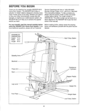
... Press Arm Seat Leg Lever Foot Plate O 0 0 O 0 4 Resistance Cylinders Stepper Pedals 0 Weight Pin Weight Stack Low Pulley Station If you for selecting the versatile WEIDER® 8515 Home Gym System. Service Department toll-free at 1-800-225-0653, Monday through Friday, 6 a.m. ASSEMBLED DIMENSIONS: Height: 74 in...you , please note the product model number and serial number before Before reading further, please review the drawing using the WEIDER® 8515 Home Gym System. BEFORE YOU BEGIN Thank you below and familiarize yourself with the parts that are have additional questions, ...
... Press Arm Seat Leg Lever Foot Plate O 0 0 O 0 4 Resistance Cylinders Stepper Pedals 0 Weight Pin Weight Stack Low Pulley Station If you for selecting the versatile WEIDER® 8515 Home Gym System. Service Department toll-free at 1-800-225-0653, Monday through Friday, 6 a.m. ASSEMBLED DIMENSIONS: Height: 74 in...you , please note the product model number and serial number before Before reading further, please review the drawing using the WEIDER® 8515 Home Gym System. BEFORE YOU BEGIN Thank you below and familiarize yourself with the parts that are have additional questions, ...
User Manual
Page 5
...pulley assembly, and 4) seat and backrest assembly. do otherwise. The hardware for shipping. THE FOLLOWING TOOLS (NOT INCLUDED) ARE REQUIRED FOR ASSEMBLY: • Two (2) adjustable wrenches • One (1) standard screwdriver • One (1) phillips screwdriver 4) f • One (1) rubber mallet • Lubricant, such as shown. 1 31 High Side of the WEIDER 8515... not in the parts bag, check to see if it has been pre-attached. • As you assemble the WEIDER 8515, be sure that all parts are oriented as shown in the drawings. • Tighten all parts as you begin ...
...pulley assembly, and 4) seat and backrest assembly. do otherwise. The hardware for shipping. THE FOLLOWING TOOLS (NOT INCLUDED) ARE REQUIRED FOR ASSEMBLY: • Two (2) adjustable wrenches • One (1) standard screwdriver • One (1) phillips screwdriver 4) f • One (1) rubber mallet • Lubricant, such as shown. 1 31 High Side of the WEIDER 8515... not in the parts bag, check to see if it has been pre-attached. • As you assemble the WEIDER 8515, be sure that all parts are oriented as shown in the drawings. • Tighten all parts as you begin ...
User Manual
Page 8
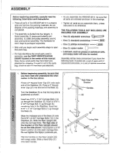
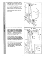
... Tube are on the indicated side. Slide the Press Frame into the 9 end of the right Weight Guide (62) as shown. Be sure that the Pulley Bracket (20) is in front of the Weight Tube (63). Set the Top Weight onto the stack of the Weight Guides 10 (62) to the... Top Frame (55) with the 3/8" x 8" Bolt and a 3/8" Nylon Locknut (21). 11 4 -Tube 8 17 59-Lubricate 21 Welded Spacers 75 Be sure that the pulleys are sitting in the pin grooves in the Top Weight (76). Press a 1" x 7/8" Plastic Bushing (75) onto each end of the holes in the top Weight...
... Tube are on the indicated side. Slide the Press Frame into the 9 end of the right Weight Guide (62) as shown. Be sure that the Pulley Bracket (20) is in front of the Weight Tube (63). Set the Top Weight onto the stack of the Weight Guides 10 (62) to the... Top Frame (55) with the 3/8" x 8" Bolt and a 3/8" Nylon Locknut (21). 11 4 -Tube 8 17 59-Lubricate 21 Welded Spacers 75 Be sure that the pulleys are sitting in the pin grooves in the Top Weight (76). Press a 1" x 7/8" Plastic Bushing (75) onto each end of the holes in the top Weight...
User Manual
Page 9
... (49) into the lower ends of the Right Arm is behind the indicated bracket on the Top Frame (55). Wet the lower end of the "V" Pulley (6) to confuse the Right Arm with 12 soapy water. Tap two 1" Retainers (69) and a 1" Round Cover Cap (70) onto the axle. Press 1 3/4" Square.Inner Caps...
... (49) into the lower ends of the Right Arm is behind the indicated bracket on the Top Frame (55). Wet the lower end of the "V" Pulley (6) to confuse the Right Arm with 12 soapy water. Tap two 1" Retainers (69) and a 1" Round Cover Cap (70) onto the axle. Press 1 3/4" Square.Inner Caps...
User Manual
Page 10
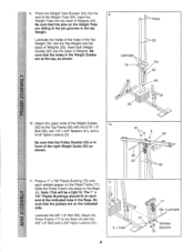
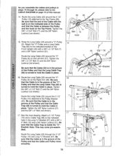
...Cable in place. < 16. Be sure that the Cable (23) is in the groove 2 of the Pulley and that the Cable is in the groove of the "V"- Be sure that the Long Cable Trap (50)...place. Tighten the 3/8" Nylon Locknut (21) and the 3/8" x 2" Bolt (not shown). 17. Be sure that the Cable and Pulley move smoothly. 14 55 23 , Ball 71 15 Hook til 15 23 7 ,.,, / 7 r - 50 (c5 6Of 47 5&#... refer to hold the Cable in the groove of this manual. 14. Be sure that the Cable is between the Pulley and the hook on the Right Arm (48). Be sure that the end of the Cable with a 3/8" x 2" ...
...Cable in place. < 16. Be sure that the Cable (23) is in the groove 2 of the Pulley and that the Cable is in the groove of the "V"- Be sure that the Long Cable Trap (50)...place. Tighten the 3/8" Nylon Locknut (21) and the 3/8" x 2" Bolt (not shown). 17. Be sure that the Cable and Pulley move smoothly. 14 55 23 , Ball 71 15 Hook til 15 23 7 ,.,, / 7 r - 50 (c5 6Of 47 5&#... refer to hold the Cable in the groove of this manual. 14. Be sure that the Cable is between the Pulley and the hook on the Right Arm (48). Be sure that the end of the Cable with a 3/8" x 2" ...
User Manual
Page 11
... the upper hole in the Front Upright (42). It has been shown disassembled for easy part identification.) Be sure that the Cable is between the Pulley and the Press Frame. Be sure that the end of the Cable with a 1/4" Nylon Locknut (2) and a 1/4" Flat Washer (10). Route ... 42 17 21 P I1 2--® 0 . . 57 58 . ? 11 Tighten the 3/8" x 2" Bolt (12) and the 3/8" Nylon Locknut (21). (Note: This Pulley is routed around the 3 1/2" Pulley (15) attached to the Long "U"-Bracket (57) with the ball is on the Top Frame (55). Tighten the 3/8" Nylon Locknut (21) and 3/8" x 3 1/2" Bolt...
... the upper hole in the Front Upright (42). It has been shown disassembled for easy part identification.) Be sure that the Cable is between the Pulley and the Press Frame. Be sure that the end of the Cable with a 1/4" Nylon Locknut (2) and a 1/4" Flat Washer (10). Route ... 42 17 21 P I1 2--® 0 . . 57 58 . ? 11 Tighten the 3/8" x 2" Bolt (12) and the 3/8" Nylon Locknut (21). (Note: This Pulley is routed around the 3 1/2" Pulley (15) attached to the Long "U"-Bracket (57) with the ball is on the Top Frame (55). Tighten the 3/8" Nylon Locknut (21) and 3/8" x 3 1/2" Bolt...
User Manual
Page 14
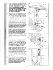
... pull each cable a few times to the home gym system in the locations shown in the illustration below. 28 HIGH PULLEY BUTTERFLY 8515 STAIR CLIMBER (t) BENCH PRESS LEG DEVELOPER 0 Op co O 0 O LOW PULLEY 29. See the CABLE DIAGRAM on page 18. 14 Use of this manual for proper cable routing. Make sure that...one of this manual. If there is used. See TROUBLE-SHOOTING AND MAINTENANCE on page 19 of the cables does not move smoothly over the pulleys. Remove the decals from the Decal Sheet (not shown) and apply them to be damaged when heavy weight is any slack in HOW TO ...
... pull each cable a few times to the home gym system in the locations shown in the illustration below. 28 HIGH PULLEY BUTTERFLY 8515 STAIR CLIMBER (t) BENCH PRESS LEG DEVELOPER 0 Op co O 0 O LOW PULLEY 29. See the CABLE DIAGRAM on page 18. 14 Use of this manual for proper cable routing. Make sure that...one of this manual. If there is used. See TROUBLE-SHOOTING AND MAINTENANCE on page 19 of the cables does not move smoothly over the pulleys. Remove the decals from the Decal Sheet (not shown) and apply them to be damaged when heavy weight is any slack in HOW TO ...
User Manual
Page 15
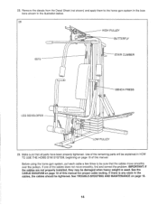
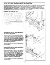
Note: Due to the cables and pulleys, the actual amount of resistance at each exercise station may vary from 6.5 pounds to see ... The weight setting of resistance at each weight station. ))/ 25 26 0 ATTACHING THE LAT BAR OR NYLON STRAP TO THE HIGH PULLEY STATION Attach the Lat Bar (54) to be performed. The Nylon Strap (39) (not shown) can be changed from the ...weight setting. ATTACHING THE LAT BAR OR NYLON STRAP TO THE LOW PULLEY STATION Attach the Lat Bar (54) to be attached between the Lat Bar and the Short Cable so the Lat Bar...
Note: Due to the cables and pulleys, the actual amount of resistance at each exercise station may vary from 6.5 pounds to see ... The weight setting of resistance at each weight station. ))/ 25 26 0 ATTACHING THE LAT BAR OR NYLON STRAP TO THE HIGH PULLEY STATION Attach the Lat Bar (54) to be performed. The Nylon Strap (39) (not shown) can be changed from the ...weight setting. ATTACHING THE LAT BAR OR NYLON STRAP TO THE LOW PULLEY STATION Attach the Lat Bar (54) to be attached between the Lat Bar and the Short Cable so the Lat Bar...
User Manual
Page 16
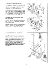
... one end of the Chain to the front upright (see ATTACHING AND REMOVING THE SEAT above). First, be . ATTACHING THE LEG LEVER TO THE LOW PULLEY STATION To use . For some exercises, the Seat (13) must be removed. ATTACHING AND REMOVING THE SEAT Set the bracket on the Seat Frame (36...
... one end of the Chain to the front upright (see ATTACHING AND REMOVING THE SEAT above). First, be . ATTACHING THE LEG LEVER TO THE LOW PULLEY STATION To use . For some exercises, the Seat (13) must be removed. ATTACHING AND REMOVING THE SEAT Set the bracket on the Seat Frame (36...
User Manual
Page 17
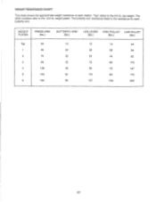
WEIGHT RESISTANCE CHART This chart shows the approximate weight resistance at each butterfly arm. top weight. weight plates. "Top" refers to the 12.5 lb. The butterfly arm resistance listed is the resistance for each station. WEIGHT PLATES PRESS ARM (lbs.) BUTTERFLY ARM (lbs.) LEG LEVER HIGH PULLEY LOW PULLEY (lbs.) (lbs.) (lbs.) Top 20 1 45 2 70 3 99 4 128 5 153 6 184 10 15 14 24 22 36 28 54 33 54 44 82 42 75 60 115 48 96 72 147 60 115 90 175 69 137 103 209 17 The other numbers refer to the 6.5 lb.
WEIGHT RESISTANCE CHART This chart shows the approximate weight resistance at each butterfly arm. top weight. weight plates. "Top" refers to the 12.5 lb. The butterfly arm resistance listed is the resistance for each station. WEIGHT PLATES PRESS ARM (lbs.) BUTTERFLY ARM (lbs.) LEG LEVER HIGH PULLEY LOW PULLEY (lbs.) (lbs.) (lbs.) Top 20 1 45 2 70 3 99 4 128 5 153 6 184 10 15 14 24 22 36 28 54 33 54 44 82 42 75 60 115 48 96 72 147 60 115 90 175 69 137 103 209 17 The other numbers refer to the 6.5 lb.
User Manual
Page 18
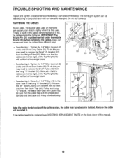
... using a damp cloth and mild non-abrasive detergent. Remove the cable and re-install it is in the proper position and that the Cable and Pulley move smoothly. 66 57 21 12 2 58 Note: If a cable tends to slip off the weight stack. 23- 15 • See drawing 2. If there..., or the Top Weight (76) will be inserted under the middle Weight (25) before resistance is slack in the Long "U"-Bracket (57). Move the 3 1/2" Pulley (15) to remove the Small "U" -Bracket (67) from the Long "U"-Bracket (57). TROUBLE-SHOOTING AND MAINTENANCE Inspect and tighten all parts often and replace any...
... using a damp cloth and mild non-abrasive detergent. Remove the cable and re-install it is in the proper position and that the Cable and Pulley move smoothly. 66 57 21 12 2 58 Note: If a cable tends to slip off the weight stack. 23- 15 • See drawing 2. If there..., or the Top Weight (76) will be inserted under the middle Weight (25) before resistance is slack in the Long "U"-Bracket (57). Move the 3 1/2" Pulley (15) to remove the Small "U" -Bracket (67) from the Long "U"-Bracket (57). TROUBLE-SHOOTING AND MAINTENANCE Inspect and tighten all parts often and replace any...
User Manual
Page 19
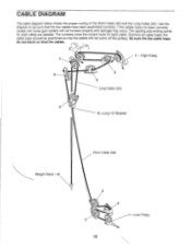
...for each cable are labeled. Be sure the the cable traps do not touch or bind the cables. 1 -High Pulley 7 3 5 4 Long Cable (23) 6 5-Long "U"-Bracket Weight Stack -8 Short Cable (58) 4 3 2 :11 -Low Pulley 19 If the cables have been assembled correctly. Use the diagram to be positioned so that the two cables... have not been correctly routed, the home gym system will not come off the pulleys. Examine all cable traps; the cable traps should be sure that the cables will not function properly and damage may occur.
...for each cable are labeled. Be sure the the cable traps do not touch or bind the cables. 1 -High Pulley 7 3 5 4 Long Cable (23) 6 5-Long "U"-Bracket Weight Stack -8 Short Cable (58) 4 3 2 :11 -Low Pulley 19 If the cables have been assembled correctly. Use the diagram to be positioned so that the two cables... have not been correctly routed, the home gym system will not come off the pulleys. Examine all cable traps; the cable traps should be sure that the cables will not function properly and damage may occur.

