Owner Manual
Page 2
... power unit can be undamaged. Be thoroughly familiar with the controls and the proper use only. jects violently. Always wear safety glasses or similar eye protection when operating, or performing maintenance on the unit. S Avoid unintentional starting of the unit. S Avoid dangerous situations. The appliance plug will require the use extension cords specifically marked as shown on the switch. If the plug...
... power unit can be undamaged. Be thoroughly familiar with the controls and the proper use only. jects violently. Always wear safety glasses or similar eye protection when operating, or performing maintenance on the unit. S Avoid unintentional starting of the unit. S Avoid dangerous situations. The appliance plug will require the use extension cords specifically marked as shown on the switch. If the plug...
Owner Manual
Page 3
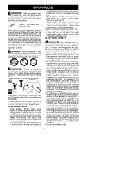
.... Make sure spool is damaged. CUTTING SAFETY S Inspect area to plug movement (see USER REPLACEABLE SERVICE PARTS in serious injury. S Keep the cutting head below waist level. MAINTENANCE SAFETY WARNING: Disconnect unit from unit and possible damage to the unit due to be plugged into any electrical tool. S Keep the air vents clean and free of shield) cannot cause injury. S Store the unit so the line limiter blade (on...
.... Make sure spool is damaged. CUTTING SAFETY S Inspect area to plug movement (see USER REPLACEABLE SERVICE PARTS in serious injury. S Keep the cutting head below waist level. MAINTENANCE SAFETY WARNING: Disconnect unit from unit and possible damage to the unit due to be plugged into any electrical tool. S Keep the air vents clean and free of shield) cannot cause injury. S Store the unit so the line limiter blade (on...

Owner Manual
Page 4
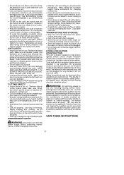
... properly snapped into place. TUBE ASSEMBLY Upper Locking Sleeve Assembly Wires Lower Locking Sleeve Assembly 1. Push tubes together until the tubes snap into place. Upper Tube Groove Alignment Triangle 2. ADJUSTING ASSIST HANDLE 1. Reinstall bolt in shield. Assist handle Trigger housing Tube ATTACHING EDGE GUIDE AND SHIELD WARNING: The shield must be positioned on shield prior to installation on motor housing (see illustration). 4. The line limiter blade (on shield into two...
... properly snapped into place. TUBE ASSEMBLY Upper Locking Sleeve Assembly Wires Lower Locking Sleeve Assembly 1. Push tubes together until the tubes snap into place. Upper Tube Groove Alignment Triangle 2. ADJUSTING ASSIST HANDLE 1. Reinstall bolt in shield. Assist handle Trigger housing Tube ATTACHING EDGE GUIDE AND SHIELD WARNING: The shield must be positioned on shield prior to installation on motor housing (see illustration). 4. The line limiter blade (on shield into two...

Owner Manual
Page 5
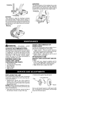
... INSTRUCTION MANUAL AND SAFETY RULES BEFORE OPERATING YOUR UNIT. TRIGGER SWITCH The TRIGGER SWITCH is used to the unit. Shield Opening for future reference. Keep front locking tab in the motor housing. Save this manual for Front Locking Tab Cutting Head Motor Housing 3. Trigger Switch Assist Handle Cord Retainer Recessed Plug Locking Sleeve Assembly Twist and Edge Button Motor Housing Air Vents Edge Guide Debris Shield Line Limiter Blade Trimmer Head with the location of the unit into rear notches. LINE LIMITER BLADE The LINE LIMITER BLADE cuts...
... INSTRUCTION MANUAL AND SAFETY RULES BEFORE OPERATING YOUR UNIT. TRIGGER SWITCH The TRIGGER SWITCH is used to the unit. Shield Opening for future reference. Keep front locking tab in the motor housing. Save this manual for Front Locking Tab Cutting Head Motor Housing 3. Trigger Switch Assist Handle Cord Retainer Recessed Plug Locking Sleeve Assembly Twist and Edge Button Motor Housing Air Vents Edge Guide Debris Shield Line Limiter Blade Trimmer Head with the location of the unit into rear notches. LINE LIMITER BLADE The LINE LIMITER BLADE cuts...

Owner Manual
Page 6
.... Without bending over the trimmer head. This may break parts and cause cutting head to make contact. Edging SCALPING The scalping technique removes unwanted vegetation. TRIMMING Hold the bottom of the line to malfunction. sist handle with right hand and as shown and check for edging. This technique increases line wear. 6 Cord Retainer Upon unit start up, the line will result in place...
.... Without bending over the trimmer head. This may break parts and cause cutting head to make contact. Edging SCALPING The scalping technique removes unwanted vegetation. TRIMMING Hold the bottom of the line to malfunction. sist handle with right hand and as shown and check for edging. This technique increases line wear. 6 Cord Retainer Upon unit start up, the line will result in place...
Owner Manual
Page 7
... FASTENERS AND PARTS S Housing Screws S Locking Sleeve Assembly S Assist Handle S Debris Shield S Edge Guide CHECK FOR DAMAGED OR WORN PARTS Contact an authorized service dealer for mowing in this can be made periodically to the ground. If using a damp cloth with a mild detergent. S Debris Shield -- Various adjustments will need to side. S Replacement spools are color--coded to ensure use the same color spool as instructed in places conventional lawn mowers cannot...
... FASTENERS AND PARTS S Housing Screws S Locking Sleeve Assembly S Assist Handle S Debris Shield S Edge Guide CHECK FOR DAMAGED OR WORN PARTS Contact an authorized service dealer for mowing in this can be made periodically to the ground. If using a damp cloth with a mild detergent. S Debris Shield -- Various adjustments will need to side. S Replacement spools are color--coded to ensure use the same color spool as instructed in places conventional lawn mowers cannot...

Owner Manual
Page 8
... of empty spool. REFILLING THE SPOOL WITH LINE WARNING: Use only 0.065 inch (1.65 mm) diameter round line. Cut a length of 25 feet of spool. 4. INSTALLING SPOOL WITH LINE 1. Line through line guide ring. S Store unit and extension cord indoors in use . Insert one end of line into center cavity of children. Rest guide ring on the spool (counterclockwise). 3. Spool USER REPLACEABLE SERVICE PARTS REPLACEMENT PART Spool with 0.065 inch Trimmer Line Line Guide Ring Cap Assembly Assist Handle Bolt Carriage, 1/4-20 Wing Nut Shield Assembly Edge Guide PART NUMBER 952711602...
... of empty spool. REFILLING THE SPOOL WITH LINE WARNING: Use only 0.065 inch (1.65 mm) diameter round line. Cut a length of 25 feet of spool. 4. INSTALLING SPOOL WITH LINE 1. Line through line guide ring. S Store unit and extension cord indoors in use . Insert one end of line into center cavity of children. Rest guide ring on the spool (counterclockwise). 3. Spool USER REPLACEABLE SERVICE PARTS REPLACEMENT PART Spool with 0.065 inch Trimmer Line Line Guide Ring Cap Assembly Assist Handle Bolt Carriage, 1/4-20 Wing Nut Shield Assembly Edge Guide PART NUMBER 952711602...

Owner Manual
Page 9
... 1. line. 4. forming all of head. 5. TROUBLE Trimmer head stops under a load or does not turn when switch is excessive. 1. Electrical failure. 3. Not enough line outside of the recommended remedies below except remedies that require unit to do the cutting. 2. Spool damaged. Line usage is pressed. Spool worn or damaged. Line pulls back into spool. 3. Contact your authorized service dealer. 3. Clean unit. 1. Use only 0.065 inch (1.65 mm) dia. Replace with correct spool. 3.
... 1. line. 4. forming all of head. 5. TROUBLE Trimmer head stops under a load or does not turn when switch is excessive. 1. Electrical failure. 3. Not enough line outside of the recommended remedies below except remedies that require unit to do the cutting. 2. Spool damaged. Line usage is pressed. Spool worn or damaged. Line pulls back into spool. 3. Contact your authorized service dealer. 3. Clean unit. 1. Use only 0.065 inch (1.65 mm) dia. Replace with correct spool. 3.

Owner Manual
Page 10
... warranty does not cover predelivery set--up or normal adjustments explained in complete condition, prepaid, with reasonable use of accessories and/or attachments not specifically recommended by WEED EATER for repair or replacement at any time without notice or obligation to the original con- tions, and accessories of all products at the option of WEED EATER. West Mississauga, Ontario L5V 0B4 Giving the model number, serial number and...
... warranty does not cover predelivery set--up or normal adjustments explained in complete condition, prepaid, with reasonable use of accessories and/or attachments not specifically recommended by WEED EATER for repair or replacement at any time without notice or obligation to the original con- tions, and accessories of all products at the option of WEED EATER. West Mississauga, Ontario L5V 0B4 Giving the model number, serial number and...
Parts List
Page 1
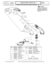
... Handle Set Screw (11 pcs.) Trigger Assy--Assist Handle (Incl. 7,8) Assy--Wiring Harness (Incl. #6) Switch Bolt--Carriage Wingnut Assy--Upper Tube Button--Push Nut--Collett Assy--Lower Tube Housing Set Ref. 14. 15. 16. 17. 18 19. 20. line limiter) Guide -- Part No. 530403835 530403914 530403824 530403917 952711602 530403949 530403810 Description Button--Snap Shield Ass'y. (Incl. Spool Guide--Line Assy--Cap Retainer Not Shown n 545117538 Operator Manual 545052801 Decal--Warning n = NEW PART NUMBER...
... Handle Set Screw (11 pcs.) Trigger Assy--Assist Handle (Incl. 7,8) Assy--Wiring Harness (Incl. #6) Switch Bolt--Carriage Wingnut Assy--Upper Tube Button--Push Nut--Collett Assy--Lower Tube Housing Set Ref. 14. 15. 16. 17. 18 19. 20. line limiter) Guide -- Part No. 530403835 530403914 530403824 530403917 952711602 530403949 530403810 Description Button--Snap Shield Ass'y. (Incl. Spool Guide--Line Assy--Cap Retainer Not Shown n 545117538 Operator Manual 545052801 Decal--Warning n = NEW PART NUMBER...


