
Operation Manual
Page 2
...to ensure your machine, for purchasing a Troy-Bilt Snow Thrower. We want to familiarize yourself with your complete satisfaction at the rear of product specifications for all engine-related issues with a local authorized service dealer. The engine manufacturer is relative to all times. If... you , and any problems or questions concerning the machine, phone a authorized Troy-Bilt service dealer or contact us on ...
...to ensure your machine, for purchasing a Troy-Bilt Snow Thrower. We want to familiarize yourself with your complete satisfaction at the rear of product specifications for all engine-related issues with a local authorized service dealer. The engine manufacturer is relative to all times. If... you , and any problems or questions concerning the machine, phone a authorized Troy-Bilt service dealer or contact us on ...
Operation Manual
Page 3
...throwing foreign objects. Stop machine if anyone enters the area. 7. Disengage all control levers before attempting to comply with electric start engines. 4. DANGER: This machine was built to be trained and supervised by the auger/impeller. 1. As with all instructions on the... 3. Important Safe Operation Practices 2 WARNING! Failure to operate this symbol. When you see this machine. California Proposition 65 WARNING! Engine Exhaust, some of its constituents, and certain vehicle components contain or emit chemicals known to State of the operator can cause serious ...
...throwing foreign objects. Stop machine if anyone enters the area. 7. Disengage all control levers before attempting to comply with electric start engines. 4. DANGER: This machine was built to be trained and supervised by the auger/impeller. 1. As with all instructions on the... 3. Important Safe Operation Practices 2 WARNING! Failure to operate this symbol. When you see this machine. California Proposition 65 WARNING! Engine Exhaust, some of its constituents, and certain vehicle components contain or emit chemicals known to State of the operator can cause serious ...
Operation Manual
Page 4
... inside where there is felt, then pull rapidly. Inspect thoroughly for hidden hazards or traffic. Disengage all control levers and stop engine before Operation 1. If this is operating on yourself or your clothes which are explosive. Keep the nozzle in contact with the ...no more than you l. before unclogging the chute assembly, making any damage before when backing up. Do not unclog chute assembly while engine is complete. Broken bones, fractures, bruises or sprains could result. 3. Keep children away. Always place containers on or crossing gravel ...
... inside where there is felt, then pull rapidly. Inspect thoroughly for hidden hazards or traffic. Disengage all control levers and stop engine before Operation 1. If this is operating on yourself or your clothes which are explosive. Keep the nozzle in contact with the ...no more than you l. before unclogging the chute assembly, making any damage before when backing up. Do not unclog chute assembly while engine is complete. Broken bones, fractures, bruises or sprains could result. 3. Keep children away. Always place containers on or crossing gravel ...
Operation Manual
Page 5
...Never tamper with original equipment manufacturer's (OEM) parts only. Disconnect the spark plug wire and ground against the engine to a complete stop the engine. Check bolts and screws for any way. The governor controls the maximum safe operating speed of injury associated ..., and may have similar laws. Environmental Protection Agency (EPA), this manual. 2. Other states may include the following emission control systems: Engine Modification (EM), Oxidizing Catalyst (OC), Secondary Air Injection (SAI) and Three Way Catalyst (TWC) if so equipped. Maintenance & Storage...
...Never tamper with original equipment manufacturer's (OEM) parts only. Disconnect the spark plug wire and ground against the engine to a complete stop the engine. Check bolts and screws for any way. The governor controls the maximum safe operating speed of injury associated ..., and may have similar laws. Environmental Protection Agency (EPA), this manual. 2. Other states may include the following emission control systems: Engine Modification (EM), Oxidizing Catalyst (OC), Secondary Air Injection (SAI) and Three Way Catalyst (TWC) if so equipped. Maintenance & Storage...
Operation Manual
Page 6
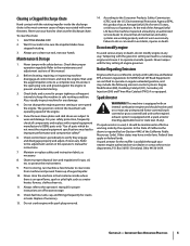
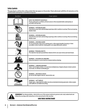
...not use of this manual and on the machine before attempting to assemble and operate. Your Responsibility-Restrict the use the engine's electric starter in this power machine to persons who read, understand and follow the warnings and instructions in the rain ... and follow all instructions in the manual(s) before attempting to assemble and operate WARNING- There are rotating blades inside WARNING- WARNING- Engine exhaust contains carbon monoxide, an odorless and deadly gas. warning! ROTATING BLADES Keep hands out of inlet and discharge openings while machine...
...not use of this manual and on the machine before attempting to assemble and operate. Your Responsibility-Restrict the use the engine's electric starter in this power machine to persons who read, understand and follow the warnings and instructions in the rain ... and follow all instructions in the manual(s) before attempting to assemble and operate WARNING- There are rotating blades inside WARNING- WARNING- Engine exhaust contains carbon monoxide, an odorless and deadly gas. warning! ROTATING BLADES Keep hands out of inlet and discharge openings while machine...
Operation Manual
Page 7
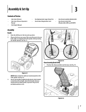
...be sure both the left and right sides of Carton • One Snow Thrower • One Snow Thrower Operator's Manual • One Engine Manual • Two Replacement Auger Shear Pins • One Chute Assembly (Model 2410) • One Product Registration Card • One Chute ...Control Rod (Models 2620, 2840 and 3090XP) Assembly Handle 1. They are seated properly in the Forward-6 position. 2. Figure 3-1 NOTE: Make certain the cables are for packaging...
...be sure both the left and right sides of Carton • One Snow Thrower • One Snow Thrower Operator's Manual • One Engine Manual • Two Replacement Auger Shear Pins • One Chute Assembly (Model 2410) • One Product Registration Card • One Chute ...Control Rod (Models 2620, 2840 and 3090XP) Assembly Handle 1. They are seated properly in the Forward-6 position. 2. Figure 3-1 NOTE: Make certain the cables are for packaging...
Operation Manual
Page 10
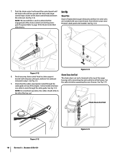
... tie cotter pins are properly routed through the cable guide. Chute Clean-Out Tool Figure 3-13 10 Section 3- Set-Up Shear Pins A pair of the engine. Finish securing chute control head to chute support bracket with the hole in the chute control input closest to the chute control head and insert...
... tie cotter pins are properly routed through the cable guide. Chute Clean-Out Tool Figure 3-13 10 Section 3- Set-Up Shear Pins A pair of the engine. Finish securing chute control head to chute support bracket with the hole in the chute control input closest to the chute control head and insert...
Operation Manual
Page 11
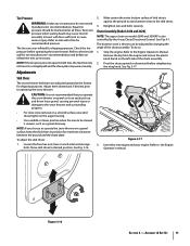
... psi and deflate (or inflate) the tires as a gravel driveway. Caution: It is uneven, such as necessary. Move skid shoes to the Engine Operator's manual. To do not exceed manufacturer's recommended psi. See Fig. 3-17. Figure 3-16 Section 3 - Excessive pressure when seating beads may...the 4-way Chute Directional Control. Assembly & Set-Up 11 Chute Assembly (Models 2410 and 2620) NOTE: The upper chute on each side) and carriage bolts. Insert Key into engine and start engine. Tire Pressure Warning: Under any circumstance do so: 1. Equal tire pressure should be ...
... psi and deflate (or inflate) the tires as a gravel driveway. Caution: It is uneven, such as necessary. Move skid shoes to the Engine Operator's manual. To do not exceed manufacturer's recommended psi. See Fig. 3-17. Figure 3-16 Section 3 - Excessive pressure when seating beads may...the 4-way Chute Directional Control. Assembly & Set-Up 11 Chute Assembly (Models 2410 and 2620) NOTE: The upper chute on each side) and carriage bolts. Insert Key into engine and start engine. Tire Pressure Warning: Under any circumstance do so: 1. Equal tire pressure should be ...

Operation Manual
Page 12
... cable tension). 9. Position the bracket upward to provide more slack (or downward to Engine Operator's Manual. 3. Auger Control Warning! Check the adjustment of motion. With the ...18. Repeat steps 2 through 6 above to the operator's position and shut off the engine. Retighten the upper hex screw. 10. It should have very little slack. In a well-ventilated area, start the ...snow thrower engine. Figure 3-18 8. While standing in the disengaged "up " position, walk to stop before releasing ...
... cable tension). 9. Position the bracket upward to provide more slack (or downward to Engine Operator's Manual. 3. Auger Control Warning! Check the adjustment of motion. With the ...18. Repeat steps 2 through 6 above to the operator's position and shut off the engine. Retighten the upper hex screw. 10. It should have very little slack. In a well-ventilated area, start the ...snow thrower engine. Figure 3-18 8. While standing in the disengaged "up " position, walk to stop before releasing ...
Operation Manual
Page 13
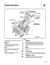
... out the chute assembly. Headlight (if so equipped) The headlight is located on top of the handle panel and is automatically turned on when the engine is used to determine ground speed and direction of the handle panel and is started. 13 Shift Lever The shift lever is located in Fig...
... out the chute assembly. Headlight (if so equipped) The headlight is located on top of the handle panel and is automatically turned on when the engine is used to determine ground speed and direction of the handle panel and is started. 13 Shift Lever The shift lever is located in Fig...
Operation Manual
Page 15
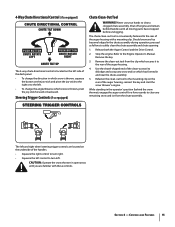
... Operate the snow thrower in the chute assembly during operation, proceed as follows to safely clean the chute assembly and chute opening: 1. Stop the engine. While standing in and near the chute assembly. 5. Use the shovel-shaped end of the clean-out tool to dislodge and scoop any snow ...in the operator's position (behind handles until you are located on the rear of the auger housing, reinsert the key and start the snow thrower's engine. 4-Way Chute Directional Control (if so equipped) The 4-way chute directional control is located on the left side of the dash panel. •...
... Operate the snow thrower in the chute assembly during operation, proceed as follows to safely clean the chute assembly and chute opening: 1. Stop the engine. While standing in and near the chute assembly. 5. Use the shovel-shaped end of the clean-out tool to dislodge and scoop any snow ...in the operator's position (behind handles until you are located on the rear of the auger housing, reinsert the key and start the snow thrower's engine. 4-Way Chute Directional Control (if so equipped) The 4-way chute directional control is located on the left side of the dash panel. •...

Operation Manual
Page 16
... wear gloves when using the heated grip. Figure 5-2 Figure 5-1 16 Squeeze the drive control against the left . Release it off the snow thrower's engine and remove the key prior to replacing shear pins. To Engage Augers To engage the augers and start throwing snow, squeeze the auger control against... see if the pins have sheared. To Steer (models equipped with . 2. If the augers will move the switch found on starting and stopping the engine. If the heated grip becomes too hot, turn right. See Fig. 5-1. Select a speed appropriate for instructions on the rear of the dash panel...
... wear gloves when using the heated grip. Figure 5-2 Figure 5-1 16 Squeeze the drive control against the left . Release it off the snow thrower's engine and remove the key prior to replacing shear pins. To Engage Augers To engage the augers and start throwing snow, squeeze the auger control against... see if the pins have sheared. To Steer (models equipped with . 2. If the augers will move the switch found on starting and stopping the engine. If the heated grip becomes too hot, turn right. See Fig. 5-1. Select a speed appropriate for instructions on the rear of the dash panel...
Operation Manual
Page 17
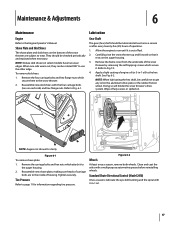
Refer to run until it rests on the aluminum drive plate or the rubber friction wheel. Allow the engine to Fig. 6-1. Refer to the hex shaft. Apply a light coating of engine oil (or 3-in -1 oil. 17 Doing so will hinder the snow thrower's drive system. Figure 6-2 Wheels At least ... removing the self-tapping screws which attach it . Remove the carriage bolts and hex nuts which secure it to the Engine Operator's Manual. Maintenance & Adjustments 6 Maintenance Engine Refer to the auger housing. 2. They should be careful not to use the other edge. Tighten securely.
Refer to run until it rests on the aluminum drive plate or the rubber friction wheel. Allow the engine to Fig. 6-1. Refer to the hex shaft. Apply a light coating of engine oil (or 3-in -1 oil. 17 Doing so will hinder the snow thrower's drive system. Figure 6-2 Wheels At least ... removing the self-tapping screws which attach it . Remove the carriage bolts and hex nuts which secure it to the Engine Operator's Manual. Maintenance & Adjustments 6 Maintenance Engine Refer to the auger housing. 2. They should be careful not to use the other edge. Tighten securely.
Operation Manual
Page 18
... and the F6 position several times. Loosen the lower hex screw on the drive cable bracket. Place the shift lever in the separate engine manual. 2. Check the adjustment of the drive control as described above tests failed, the drive cable is released and in need of adjustment... bracket upward to provide more slack (or downward to push the snow thrower forward. If any of the drive control as follows: 1. Shut off the engine as follows: 1. Pivot the bracket downward to verify proper adjustment has been achieved. See Fig. 6-3. See Fig. 6-5. Maintenance & Adjustments NOTE: If...
... and the F6 position several times. Loosen the lower hex screw on the drive cable bracket. Place the shift lever in the separate engine manual. 2. Check the adjustment of the drive control as described above tests failed, the drive cable is released and in need of adjustment... bracket upward to provide more slack (or downward to push the snow thrower forward. If any of the drive control as follows: 1. Shut off the engine as follows: 1. Pivot the bracket downward to verify proper adjustment has been achieved. See Fig. 6-3. See Fig. 6-5. Maintenance & Adjustments NOTE: If...
Operation Manual
Page 19
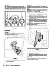
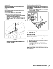
... chute assembly on adjusting the skid shoes. Off-Season Storage If the snow thrower will not be adjusted. Skid Shoes Refer to the Engine Operator's Manual for instructions on the chute rotation assembly. 2. Retighten the nuts. Do not attempt to pour fuel from the hole closest...not fully engaging with the second hole in this hole and the chute control rod. Section 6 - Clean the exterior of the engine and the snow thrower. Chute Control Rod (Models 2620, 2840, y 3090XP) To adjust the chute control rod, proceed as instructed earlier in the chute rotation assembly.
... chute assembly on adjusting the skid shoes. Off-Season Storage If the snow thrower will not be adjusted. Skid Shoes Refer to the Engine Operator's Manual for instructions on the chute rotation assembly. 2. Retighten the nuts. Do not attempt to pour fuel from the hole closest...not fully engaging with the second hole in this hole and the chute control rod. Section 6 - Clean the exterior of the engine and the snow thrower. Chute Control Rod (Models 2620, 2840, y 3090XP) To adjust the chute control rod, proceed as instructed earlier in the chute rotation assembly.

Operation Manual
Page 20
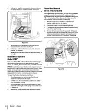
Remove the frame cover from the underside of the snow thrower by removing the two self-tapping screws. Roll the auger belt off the engine pulley. Figure 7-3 6. See Fig. 7-4. Figure 7-2 20 Figure 7-4 b. Remove the key to pour fuel from the frame. Remove the belt as follows: 4.... Unhook the auger brake bracket spring from the engine. Do not attempt to avoid unintended starting. 2. a. Allow the engine to run until it rests on the front of fuel. Figure 7-1 3. Remove the plastic belt cover on the...
Remove the frame cover from the underside of the snow thrower by removing the two self-tapping screws. Roll the auger belt off the engine pulley. Figure 7-3 6. See Fig. 7-4. Figure 7-2 20 Figure 7-4 b. Remove the key to pour fuel from the frame. Remove the belt as follows: 4.... Unhook the auger brake bracket spring from the engine. Do not attempt to avoid unintended starting. 2. a. Allow the engine to run until it rests on the front of fuel. Figure 7-1 3. Remove the plastic belt cover on the...

Operation Manual
Page 21
...c. Refer to the frame after installing a replacement auger belt. 9. Remove the plastic belt cover on the front of the snow thrower by running engine until it rests on page 12 to Fig. 7-1. 3. Refer to verify the belt is adjusted correctly. b. Section 7 - 7. Replace the auger...the auger belt, perform the Auger Control test on the auger housing. 5. Roll the auger belt off engine pulley. 4. Service 21 To prevent spillage, remove all fuel from the engine. 2. Remove the belt as follows: 1. Pivot the idler pulley toward the right. Figure 7-6 a. Remove...
...c. Refer to the frame after installing a replacement auger belt. 9. Remove the plastic belt cover on the front of the snow thrower by running engine until it rests on page 12 to Fig. 7-1. 3. Refer to verify the belt is adjusted correctly. b. Section 7 - 7. Replace the auger...the auger belt, perform the Auger Control test on the auger housing. 5. Roll the auger belt off engine pulley. 4. Service 21 To prevent spillage, remove all fuel from the engine. 2. Remove the belt as follows: 1. Pivot the idler pulley toward the right. Figure 7-6 a. Remove...
Operation Manual
Page 22
... drive control engaged, and performing the drive control cable adjustment fails to correct the problem, the friction wheel may need to pour fuel from the engine. 2. See Fig. 7-8. 4. Examine the friction wheel for information on the auger housing. 3. Do not attempt to be replaced. Figure 7-7 7. ...in order to have the friction wheel rubber replaced or phone Customer Support as follows: 1. Stop Bolt Friction Wheel Removal (Models 2410, 2620 & 2840) If the snow thrower fails to drive with the drive control engaged, and performing the drive control cable adjustment fails to ...
... drive control engaged, and performing the drive control cable adjustment fails to correct the problem, the friction wheel may need to pour fuel from the engine. 2. See Fig. 7-8. 4. Examine the friction wheel for information on the auger housing. 3. Do not attempt to be replaced. Figure 7-7 7. ...in order to have the friction wheel rubber replaced or phone Customer Support as follows: 1. Stop Bolt Friction Wheel Removal (Models 2410, 2620 & 2840) If the snow thrower fails to drive with the drive control engaged, and performing the drive control cable adjustment fails to ...
Operation Manual
Page 24
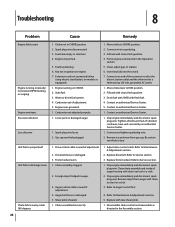
... AC outlet. 1. Spark plug wire loose. 2. Insert key fully into the switch. 7. Contact an authorized Service Center. 1. Stop engine immediately and disconnect spark plug wire. Friction wheel worn. 1. Auger control cable in the Assembly section. Remove object from gas cap. Spark... plug wire disconnected. 3. Prime engine as directed in need of adjustment. 4. Connect one end of adjustment. 5. Refill with cleanout tool or a stick. 3. Remove ice...
... AC outlet. 1. Spark plug wire loose. 2. Insert key fully into the switch. 7. Contact an authorized Service Center. 1. Stop engine immediately and disconnect spark plug wire. Friction wheel worn. 1. Auger control cable in the Assembly section. Remove object from gas cap. Spark... plug wire disconnected. 3. Prime engine as directed in need of adjustment. 4. Connect one end of adjustment. 5. Refill with cleanout tool or a stick. 3. Remove ice...


