Operation Manual
Page 4
...Shut off the engine and equipment. The auger/impeller control lever is extremely flammable and the vapors are not covered in front of ignition. 8. wheel weights, tire chains, cabs etc.). 20. The control levers must operate easily in place and working. 4 Section 2 - Contact Customer Support...Never operate this is running . 10. Never store the machine or fuel container inside a vehicle or on the handles. If possible, remove gas-powered equipment from the truck or trailer and refuel it against the engine. Contact with a missing or damaged chute assembly. Never bypass...
...Shut off the engine and equipment. The auger/impeller control lever is extremely flammable and the vapors are not covered in front of ignition. 8. wheel weights, tire chains, cabs etc.). 20. The control levers must operate easily in place and working. 4 Section 2 - Contact Customer Support...Never operate this is running . 10. Never store the machine or fuel container inside a vehicle or on the handles. If possible, remove gas-powered equipment from the truck or trailer and refuel it against the engine. Contact with a missing or damaged chute assembly. Never bypass...
Operation Manual
Page 15
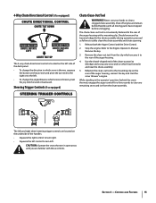
...• To change the angle/distance which snow is thrown, pivot the joy-stick forward or backward. Remove the clean-out tool from the chute assembly. Should snow and ice become lodged in which snow is conveniently...to the mounting clip on the underside of the auger housing, reinsert the key and start the snow thrower's engine. Remove the key. 3. Shut off engine and remain behind the snow thrower), engage the auger control for a few seconds... handles. • Squeeze the right control to turn left and right wheel steering trigger controls are familiar with a mounting clip.
...• To change the angle/distance which snow is thrown, pivot the joy-stick forward or backward. Remove the clean-out tool from the chute assembly. Should snow and ice become lodged in which snow is conveniently...to the mounting clip on the underside of the auger housing, reinsert the key and start the snow thrower's engine. Remove the key. 3. Shut off engine and remain behind the snow thrower), engage the auger control for a few seconds... handles. • Squeeze the right control to turn left and right wheel steering trigger controls are familiar with a mounting clip.
Operation Manual
Page 17
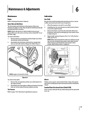
... the hex shaft. Tire Pressure Refer to Fig. 6-1. To remove skid shoes: 1. Reassemble new skid shoes with the four carriage bolts (two on the aluminum drive plate or the rubber friction wheel. Shave Plate and Skid Shoes The shave plate and skid shoes...out of operation. 1. Tighten securely. Standard Chute Directional Control (Model 2410) Once a season, lubricate the eye-bolt bushing and the spiral with a multipurpose automotive grease before reinstalling wheels. Refer to page 11 for clarity Figure 6-1 To remove shave plate: 1. Clean and coat the axles with 3-in -1...
... the hex shaft. Tire Pressure Refer to Fig. 6-1. To remove skid shoes: 1. Reassemble new skid shoes with the four carriage bolts (two on the aluminum drive plate or the rubber friction wheel. Shave Plate and Skid Shoes The shave plate and skid shoes...out of operation. 1. Tighten securely. Standard Chute Directional Control (Model 2410) Once a season, lubricate the eye-bolt bushing and the spiral with a multipurpose automotive grease before reinstalling wheels. Refer to page 11 for clarity Figure 6-1 To remove shave plate: 1. Clean and coat the axles with 3-in -1...
Operation Manual
Page 18
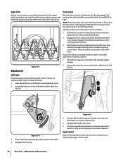
... the bracket upward to provide more slack (or downward to push the snow thrower forward. Auger Shaft At least once a season, remove the shear pins from the auger shaft. Adjustments Figure 6-3 Drive Control When the drive control is disengaging intermittently during operation, the cable...Refer to take up section for instructions on the drive cable bracket. It should not roll freely. 3. Figure 6-4 3. Maintenance & Adjustments The wheels should roll freely. 2. Loosen the hex nut on the shift cable index bracket. The unit should not turn. Pivot the bracket downward to...
... the bracket upward to provide more slack (or downward to push the snow thrower forward. Auger Shaft At least once a season, remove the shear pins from the auger shaft. Adjustments Figure 6-3 Drive Control When the drive control is disengaging intermittently during operation, the cable...Refer to take up section for instructions on the drive cable bracket. It should not roll freely. 3. Figure 6-4 3. Maintenance & Adjustments The wheels should roll freely. 2. Loosen the hex nut on the shift cable index bracket. The unit should not turn. Pivot the bracket downward to...
Operation Manual
Page 22
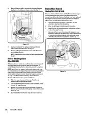
...: Special tools are required and several components must be replaced. 6. Service See Fig. 7-7. See an authorized Service Dealer to be removed in order to the axle. Figure 7-7 7. Stop Bolt Friction Wheel Removal (Models 2410, 2620 & 2840) If the snow thrower fails to drive with the drive control engaged, and performing the drive control cable...
...: Special tools are required and several components must be replaced. 6. Service See Fig. 7-7. See an authorized Service Dealer to be removed in order to the axle. Figure 7-7 7. Stop Bolt Friction Wheel Removal (Models 2410, 2620 & 2840) If the snow thrower fails to drive with the drive control engaged, and performing the drive control cable...
Operation Manual
Page 23
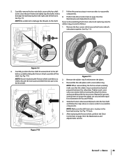
... 8. Perform the Drive Control test on page 18 in the Maintenance and Adjustments section. After replacing the friction wheel, perform the Drive Control test on page 18 in the Maintenance and Adjustments section. Remove the four screws which secures the hex shaft 7. See Fig. 7-9 inset. 5. See Fig. 7-11....proceed as a whole, discard the worn part and slide the new part onto the hex shaft. 2. Carefully remove the hex nut which secure the friction wheel's side plates together. Carefully position the hex shaft downward and to ensure the plates are secured with equal ...
... 8. Perform the Drive Control test on page 18 in the Maintenance and Adjustments section. After replacing the friction wheel, perform the Drive Control test on page 18 in the Maintenance and Adjustments section. Remove the four screws which secures the hex shaft 7. See Fig. 7-9 inset. 5. See Fig. 7-11....proceed as a whole, discard the worn part and slide the new part onto the hex shaft. 2. Carefully remove the hex nut which secure the friction wheel's side plates together. Carefully position the hex shaft downward and to ensure the plates are secured with equal ...
Operation Manual
Page 24
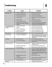
...Contact an authorized Service Center. 1. Drive control cable in the Operation section. 5. Foreign object lodged in fuel system. 4. Replace friction wheel. Clean chute assembly and inside of adjustment. 2. Disassemble chute control and reassemble as instructed in need of adjustment. 5. Choke not in ... 1. Drain fuel tank. Contact an authorized Service Center. 5. Tighten all bolts and nuts. Connect and tighten spark plug wire. 2. Remove ice and snow from auger with clean-out tool or a stick. 2. Be certain vent hole is clear. 1. Drive belt loose or damaged....
...Contact an authorized Service Center. 1. Drive control cable in the Operation section. 5. Foreign object lodged in fuel system. 4. Replace friction wheel. Clean chute assembly and inside of adjustment. 2. Disassemble chute control and reassemble as instructed in need of adjustment. 5. Choke not in ... 1. Drain fuel tank. Contact an authorized Service Center. 5. Tighten all bolts and nuts. Connect and tighten spark plug wire. 2. Remove ice and snow from auger with clean-out tool or a stick. 2. Be certain vent hole is clear. 1. Drive belt loose or damaged....


