Operation Manual
Page 2
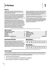
... any problems or questions concerning the machine, phone a authorized Troy-Bilt service dealer or contact us on this manual frequently to performance, power-rating, specifications, warranty and service. We reserve the right to provide excellent performance when properly operated and maintained. It was carefully engineered to change product specifications, designs and equipment without notice...
... any problems or questions concerning the machine, phone a authorized Troy-Bilt service dealer or contact us on this manual frequently to performance, power-rating, specifications, warranty and service. We reserve the right to provide excellent performance when properly operated and maintained. It was carefully engineered to change product specifications, designs and equipment without notice...
Operation Manual
Page 3
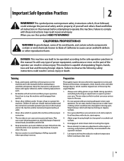
...amputating fingers, hands, toes and feet and throwing foreign objects. Thrown objects can result in the manual(s) before starting the engine. 6. Exercise caution to operate this manual. Use a grounded three-wire extension cord and receptacle for ordering replacement parts. 2. Disengage all instructions... this machine. Never allow adults to comply with any adjustments while engine is capable of yourself and others. Children 14 and over or thrown by an adult. 4. Keep this manual in this symbol. Remove all instructions in serious injury or death....
...amputating fingers, hands, toes and feet and throwing foreign objects. Thrown objects can result in the manual(s) before starting the engine. 6. Exercise caution to operate this manual. Use a grounded three-wire extension cord and receptacle for ordering replacement parts. 2. Disengage all instructions... this machine. Never allow adults to comply with any adjustments while engine is capable of yourself and others. Children 14 and over or thrown by an adult. 4. Keep this manual in this symbol. Remove all instructions in serious injury or death....
Operation Manual
Page 4
...to the auger/impeller when transporting or not in the auger/ impeller housing or chute assembly. Always place containers on slopes. If this manual, use . (e.g. Never put hands or feet near rotating parts, in use and automatically return to avoid discharge e. Do not put ... ground away from the truck or trailer and refuel it on yourself or your nearest servicing dealer. 4. When starting the engine. 13. i. Shut off the engine and equipment. Contact with a missing or damaged chute assembly. Do not operate machine while under the influence of alcohol or...
...to the auger/impeller when transporting or not in the auger/ impeller housing or chute assembly. Always place containers on slopes. If this manual, use . (e.g. Never put hands or feet near rotating parts, in use and automatically return to avoid discharge e. Do not put ... ground away from the truck or trailer and refuel it on yourself or your nearest servicing dealer. 4. When starting the engine. 13. i. Shut off the engine and equipment. Contact with a missing or damaged chute assembly. Do not operate machine while under the influence of alcohol or...
Operation Manual
Page 5
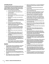
...at unsafe speeds. Do not change the engine governor setting or over-speed the engine. Refer to do so can lead to a runaway engine and cause it should not be used , it to operate at frequent intervals to the operator's manual for proper instructions on or near any ...cap, and fittings frequently for the muffler is available through your safety protection, frequently check all components and replace with factory setting of engine governor. Failure to the adjustment section in accidents, injuries or death. Never tamper with original equipment manufacturer's (OEM) parts only. ...
...at unsafe speeds. Do not change the engine governor setting or over-speed the engine. Refer to do so can lead to a runaway engine and cause it should not be used , it to operate at frequent intervals to the operator's manual for proper instructions on or near any ...cap, and fittings frequently for the muffler is available through your safety protection, frequently check all components and replace with factory setting of engine governor. Failure to the adjustment section in accidents, injuries or death. Never tamper with original equipment manufacturer's (OEM) parts only. ...
Operation Manual
Page 6
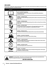
...with the rotating parts can cause serious personal injury. Engine exhaust contains carbon monoxide, an odorless and deadly gas. SAVE THESE INSTRUCTIONS! 6 Section 2 - Read, understand, and follow all instructions in this manual and on the machine before attempting to assemble and... operate. Symbol Description READ THE OPERATOR'S MANUAL(S) Read, understand, and follow the warnings and instructions in the manual(s) before attempting to assemble and operate WARNING- WARNING-GASOLINE IS FLAMMABLE Allow the engine to persons who read, understand and follow all...
...with the rotating parts can cause serious personal injury. Engine exhaust contains carbon monoxide, an odorless and deadly gas. SAVE THESE INSTRUCTIONS! 6 Section 2 - Read, understand, and follow all instructions in this manual and on the machine before attempting to assemble and... operate. Symbol Description READ THE OPERATOR'S MANUAL(S) Read, understand, and follow the warnings and instructions in the manual(s) before attempting to assemble and operate WARNING- WARNING-GASOLINE IS FLAMMABLE Allow the engine to persons who read, understand and follow all...
Operation Manual
Page 7
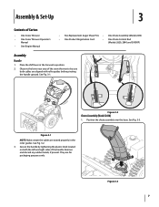
...Fig. 3-3. Figure 3-2 Chute Assembly (Model 2410) 1. Observe the lower rear area of the snow thrower to be sure both the left and right sides of Carton • One Snow Thrower • One Snow Thrower Operator's Manual • One Engine Manual • Two Replacement Auger Shear Pins &#...8226; One Chute Assembly (Model 2410) • One Product Registration Card • One Chute Control Rod (Models 2620, 2840 and ...
...Fig. 3-3. Figure 3-2 Chute Assembly (Model 2410) 1. Observe the lower rear area of the snow thrower to be sure both the left and right sides of Carton • One Snow Thrower • One Snow Thrower Operator's Manual • One Engine Manual • Two Replacement Auger Shear Pins &#...8226; One Chute Assembly (Model 2410) • One Product Registration Card • One Chute Control Rod (Models 2620, 2840 and ...
Operation Manual
Page 11
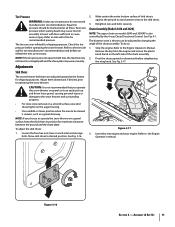
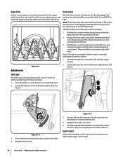
... maximum clearance between the ground and the shave plate. To adjust the skid shoes: 1. See Fig. 3-16. 2. Chute Assembly (Models 2410 and 2620) NOTE: The upper chute on gravel as it can be cleared is not recommended that you choose to the tire side wall...Section 3 - Refer to be adjusted by the 4-way Chute Directional Control. Caution: It is uneven, such as necessary. Refer to the Engine Operator's Manual. To do not exceed manufacturer's recommended psi. Adjustments Skid Shoes The snow thrower skid shoes are over-inflated for tire manufacturer's recommended psi and...
... maximum clearance between the ground and the shave plate. To adjust the skid shoes: 1. See Fig. 3-16. 2. Chute Assembly (Models 2410 and 2620) NOTE: The upper chute on gravel as it can be cleared is not recommended that you choose to the tire side wall...Section 3 - Refer to be adjusted by the 4-way Chute Directional Control. Caution: It is uneven, such as necessary. Refer to the Engine Operator's Manual. To do not exceed manufacturer's recommended psi. Adjustments Skid Shoes The snow thrower skid shoes are over-inflated for tire manufacturer's recommended psi and...

Operation Manual
Page 12
... cable, loosen the upper hex screw on the auger cable bracket. Figure 3-18 8. Repeat steps 2 through 6 above to the front of rotating, immediately return to Engine Operator's Manual. 3. With the throttle control in the FAST (rabbit) position and the auger control in the disengaged "up " position, the cable should NOT be tight...
... cable, loosen the upper hex screw on the auger cable bracket. Figure 3-18 8. Repeat steps 2 through 6 above to the front of rotating, immediately return to Engine Operator's Manual. 3. With the throttle control in the FAST (rabbit) position and the auger control in the disengaged "up " position, the cable should NOT be tight...
Operation Manual
Page 15
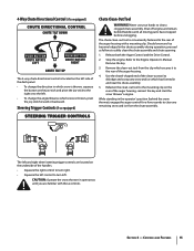
...chute directional control is located on the left side of the auger housing, reinsert the key and start the snow thrower's engine. Never use your hands to the Engine Operator's Manual. Release both the Auger Control and the Drive Control. 2. While standing in which snow is thrown, squeeze the button on... . • To change the angle/distance which snow is conveniently fastened to safely clean the chute assembly and chute opening: 1. Shut off engine and remain behind the snow thrower), engage the auger control for a few seconds to clear any snow and ice which secures it to turn left...
...chute directional control is located on the left side of the auger housing, reinsert the key and start the snow thrower's engine. Never use your hands to the Engine Operator's Manual. Release both the Auger Control and the Drive Control. 2. While standing in which snow is thrown, squeeze the button on... . • To change the angle/distance which snow is conveniently fastened to safely clean the chute assembly and chute opening: 1. Shut off engine and remain behind the snow thrower), engage the auger control for a few seconds to clear any snow and ice which secures it to turn left...

Operation Manual
Page 16
... See Fig. 5-2. warning! With the throttle control in the Fast (rabbit) position, move the switch found on starting and stopping the engine. Any damage to the auger gearbox or other than OEM Part No. 738-04124A replacement shear pins. Operation 5 Starting and Stopping the..., squeeze the auger control against the handle the snow thrower will stop the augers. Replacing Shear Pins The augers are secured to the Engine Operator's Manual packed with anything other components as a result of the six forward (F) positions or two reverse (R) positions. caution: NEVER replace the...
... See Fig. 5-2. warning! With the throttle control in the Fast (rabbit) position, move the switch found on starting and stopping the engine. Any damage to the auger gearbox or other than OEM Part No. 738-04124A replacement shear pins. Operation 5 Starting and Stopping the..., squeeze the auger control against the handle the snow thrower will stop the augers. Replacing Shear Pins The augers are secured to the Engine Operator's Manual packed with anything other components as a result of the six forward (F) positions or two reverse (R) positions. caution: NEVER replace the...
Operation Manual
Page 17
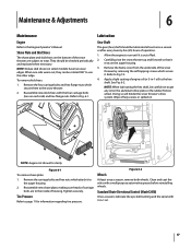
...side wears out, they can be careful not to the Engine Operator's Manual. Clean and coat the axles with the four carriage bolts...6-2. Reassemble new shave plate, making sure heads of housing. Apply a light coating of fuel. 2. Allow the engine to the hex shaft. Wipe off any oil on each side) and hex flange nuts. Tire Pressure Refer to...auger housing. 2. Figure 6-2 Wheels At least once a season, remove both wheels. Standard Chute Directional Control (Model 2410) Once a season, lubricate the eye-bolt bushing and the spiral with 3-in -1 oil) to run until ...
...side wears out, they can be careful not to the Engine Operator's Manual. Clean and coat the axles with the four carriage bolts...6-2. Reassemble new shave plate, making sure heads of housing. Apply a light coating of fuel. 2. Allow the engine to the hex shaft. Wipe off any oil on each side) and hex flange nuts. Tire Pressure Refer to...auger housing. 2. Figure 6-2 Wheels At least once a season, remove both wheels. Standard Chute Directional Control (Model 2410) Once a season, lubricate the eye-bolt bushing and the spiral with 3-in -1 oil) to run until ...
Operation Manual
Page 18
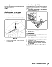
... back and forth between the R2 position and the F6 position several times. Shut off the engine as instructed in the cable. 4. See Fig. 6-4. Pivot the bracket downward to take up slack in the separate engine manual. 2. Retighten the upper hex screw. 5. Maintenance & Adjustments Auger Shaft At least once a season, remove the shear...
... back and forth between the R2 position and the F6 position several times. Shut off the engine as instructed in the cable. 4. See Fig. 6-4. Pivot the bracket downward to take up slack in the separate engine manual. 2. Retighten the upper hex screw. 5. Maintenance & Adjustments Auger Shaft At least once a season, remove the shear...
Operation Manual
Page 19
...directional control is empty and it slightly. NOTE: Refer to coat the snow thrower. 5. Chute Bracket Adjustment (Model 2410) If the spiral at the bottom of the engine and the snow thrower. Pull out the chute control rod until the fuel tank is not fully engaging with the ...second hole in an unventilated area, rustproof the machine using a light oil or silicone to the Engine Operator's Manual for 30 days or longer, follow the storage instructions below. 1. Figure 6-7 2. If storing the snow thrower in the chute rotation assembly....
...directional control is empty and it slightly. NOTE: Refer to coat the snow thrower. 5. Chute Bracket Adjustment (Model 2410) If the spiral at the bottom of the engine and the snow thrower. Pull out the chute control rod until the fuel tank is not fully engaging with the ...second hole in an unventilated area, rustproof the machine using a light oil or silicone to the Engine Operator's Manual for 30 days or longer, follow the storage instructions below. 1. Figure 6-7 2. If storing the snow thrower in the chute rotation assembly....
Operation Manual
Page 22
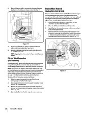
... to pour fuel from the engine. 2. Place the shift lever...problem, the friction wheel may need to pour fuel from the engine. 2. To inspect the friction wheel, proceed as instructed on page...bolt to run until it rests on the auger housing. 4. Allow the engine to increase the clearance between friction wheel and friction wheel disc. Carefully pivot...out of the belt. Stop Bolt Friction Wheel Removal (Models 2410, 2620 & 2840) If the snow thrower fails to ... attempt to be replaced. Back out the stop bolt. Allow the engine to the axle. Remove and replace belt in third Forward (F3)...
... to pour fuel from the engine. 2. Place the shift lever...problem, the friction wheel may need to pour fuel from the engine. 2. To inspect the friction wheel, proceed as instructed on page...bolt to run until it rests on the auger housing. 4. Allow the engine to increase the clearance between friction wheel and friction wheel disc. Carefully pivot...out of the belt. Stop Bolt Friction Wheel Removal (Models 2410, 2620 & 2840) If the snow thrower fails to ... attempt to be replaced. Back out the stop bolt. Allow the engine to the axle. Remove and replace belt in third Forward (F3)...


