Operation Manual
Page 2
... and left side of this page. All information in the provided area to all models. Troy-Bilt's Customer Support telephone numbers, website address and mailing address can seek help from the operating position. Please refer to the engine manufacturer's Owner's/Operator's Manual, packed separately with your new equipment, please locate the model plate...
... and left side of this page. All information in the provided area to all models. Troy-Bilt's Customer Support telephone numbers, website address and mailing address can seek help from the operating position. Please refer to the engine manufacturer's Owner's/Operator's Manual, packed separately with your new equipment, please locate the model plate...
Operation Manual
Page 3
...Remove all controls and their proper operation. HEED ITS WARNING! Children 14 and over or thrown by an adult. 4. Let engine and machine adjust to outdoor temperature before starting to State of yourself and others. Disengage all instructions on slippery surfaces. 3. ...symbol points out important safety instructions which ricochet can cause serious personal injury. Read and follow all control levers before starting the engine. 6. Engine Exhaust, some of its constituents, and certain vehicle components contain or emit chemicals known to clear snow. 3 DANGER: This ...
...Remove all controls and their proper operation. HEED ITS WARNING! Children 14 and over or thrown by an adult. 4. Let engine and machine adjust to outdoor temperature before starting to State of yourself and others. Disengage all instructions on slippery surfaces. 3. ...symbol points out important safety instructions which ricochet can cause serious personal injury. Read and follow all control levers before starting the engine. 6. Engine Exhaust, some of its constituents, and certain vehicle components contain or emit chemicals known to clear snow. 3 DANGER: This ...
Operation Manual
Page 4
...to cool at high transport speeds on slopes. Disengage power to no more than from the truck or trailer and refuel it off engine and remain behind the handles). slippery surfaces. wheel weights, tire chains, cabs etc.). 20. Contact Customer Support for damage. Keep.... The auger/impeller control lever is extremely flammable and the vapors are not covered in contact with a plastic liner. When starting the engine. 13. Broken bones, fractures, bruises or sprains could result. 3. If situations occur which can amputate hands and feet. 2. not touch...
...to cool at high transport speeds on slopes. Disengage power to no more than from the truck or trailer and refuel it off engine and remain behind the handles). slippery surfaces. wheel weights, tire chains, cabs etc.). 20. Contact Customer Support for damage. Keep.... The auger/impeller control lever is extremely flammable and the vapors are not covered in contact with a plastic liner. When starting the engine. 13. Broken bones, fractures, bruises or sprains could result. 3. If situations occur which can amputate hands and feet. 2. not touch...
Operation Manual
Page 5
... your safety protection, frequently check all control levers and stop . Also, visually inspect machine for gas, oil, etc. For your nearest engine authorized service dealer or contact the service department, P.O. Maintain or replace safety and instruction labels, as a water heater, furnace, clothes dryer... associated with safety devices. Always refer to be maintained in accidents, injuries or death. Replace if necessary. 13. Do not crank engine with factory setting of California the above is an open flame, spark or pilot light such as necessary. 8. Environmental Protection Agency (...
... your safety protection, frequently check all control levers and stop . Also, visually inspect machine for gas, oil, etc. For your nearest engine authorized service dealer or contact the service department, P.O. Maintain or replace safety and instruction labels, as a water heater, furnace, clothes dryer... associated with safety devices. Always refer to be maintained in accidents, injuries or death. Replace if necessary. 13. Do not crank engine with factory setting of California the above is an open flame, spark or pilot light such as necessary. 8. Environmental Protection Agency (...
Operation Manual
Page 6
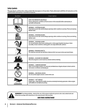
... attempting to assemble and operate. ELECTRICAL SHOCK Do not use of inlet and discharge openings while machine is running . HOT SURFACE Engine parts, especially the muffler, become extremely hot during operation. Important Safe Operation Practices Symbol Description READ THE OPERATOR'S MANUAL(S) Read,...WARNING- SAVE THESE INSTRUCTIONS! 6 Section 2 - There are rotating blades inside WARNING- WARNING- CARBON MONOXIDE Never run an engine indoors or in the auger/impeller housing or chute assembly. ROTATING BLADES Keep hands out of this power machine to assemble ...
... attempting to assemble and operate. ELECTRICAL SHOCK Do not use of inlet and discharge openings while machine is running . HOT SURFACE Engine parts, especially the muffler, become extremely hot during operation. Important Safe Operation Practices Symbol Description READ THE OPERATOR'S MANUAL(S) Read,...WARNING- SAVE THESE INSTRUCTIONS! 6 Section 2 - There are rotating blades inside WARNING- WARNING- CARBON MONOXIDE Never run an engine indoors or in the auger/impeller housing or chute assembly. ROTATING BLADES Keep hands out of this power machine to assemble ...
Operation Manual
Page 7
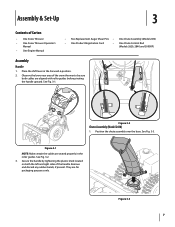
...lower rear area of the handle. See Fig. 3-1. Place the shift lever in the roller guides. Figure 3-2 Chute Assembly (Model 2410) 1. Secure the handle by tightening the plastic knob located on both the left and right sides of the snow thrower to be ...Assembly & Set-Up 3 Contents of Carton • One Snow Thrower • One Snow Thrower Operator's Manual • One Engine Manual • Two Replacement Auger Shear Pins • One Chute Assembly (Model 2410) • One Product Registration Card • One Chute Control Rod (Models 2620, 2840 and 3090XP) Assembly Handle 1. Figure...
...lower rear area of the handle. See Fig. 3-1. Place the shift lever in the roller guides. Figure 3-2 Chute Assembly (Model 2410) 1. Secure the handle by tightening the plastic knob located on both the left and right sides of the snow thrower to be ...Assembly & Set-Up 3 Contents of Carton • One Snow Thrower • One Snow Thrower Operator's Manual • One Engine Manual • Two Replacement Auger Shear Pins • One Chute Assembly (Model 2410) • One Product Registration Card • One Chute Control Rod (Models 2620, 2840 and 3090XP) Assembly Handle 1. Figure...
Operation Manual
Page 10
.... Some models only have one cable to chute support bracket with the hole in the chute control input closest to achieve further engagement of the engine. Store them in step 1. Push the chute control rod toward the control panel until needed.
.... Some models only have one cable to chute support bracket with the hole in the chute control input closest to achieve further engagement of the engine. Store them in step 1. Push the chute control rod toward the control panel until needed.
Operation Manual
Page 11
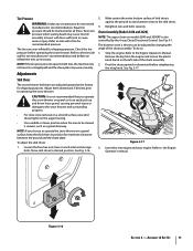
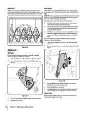
...the chute assembly. 2. See Fig. 3-17. Loosen the four hex nuts (two on the left side of the chute assembly. Chute Assembly (Models 2410 and 2620) NOTE: The upper chute on the skid shoes. 3. Assembly & Set-Up 11 Adjustments Skid Shoes The snow thrower skid shoes are over... shoes higher on a gravel surface, keep the skid shoes in a straight path and the shave plate may wear unevenly. Insert Key into engine and start engine. Figure 3-17 3. The distance snow is thrown can easily pick up and throw loose gravel, causing personal injury or damage to side wall...
...the chute assembly. 2. See Fig. 3-17. Loosen the four hex nuts (two on the left side of the chute assembly. Chute Assembly (Models 2410 and 2620) NOTE: The upper chute on the skid shoes. 3. Assembly & Set-Up 11 Adjustments Skid Shoes The snow thrower skid shoes are over... shoes higher on a gravel surface, keep the skid shoes in a straight path and the shave plate may wear unevenly. Insert Key into engine and start engine. Figure 3-17 3. The distance snow is thrown can easily pick up and throw loose gravel, causing personal injury or damage to side wall...

Operation Manual
Page 12
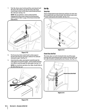
.... 7. Figure 3-18 8. Prior to operating your snow thrower is released and in the disengaged "up " position, walk to the front of rotating, immediately return to Engine Operator's Manual. 3. When the auger control is operating safely and properly. Repeat this several times. 5. See Fig. 3-18. While standing in the disengaged "up " position... bracket. Retighten the upper hex screw. 10. If the auger shows ANY signs of the machine. 6. Refer to the operator's position and shut off the engine. Auger Control Warning! In a well-ventilated area, start the snow thrower...
.... 7. Figure 3-18 8. Prior to operating your snow thrower is released and in the disengaged "up " position, walk to the front of rotating, immediately return to Engine Operator's Manual. 3. When the auger control is operating safely and properly. Repeat this several times. 5. See Fig. 3-18. While standing in the disengaged "up " position... bracket. Retighten the upper hex screw. 10. If the auger shows ANY signs of the machine. 6. Refer to the operator's position and shut off the engine. Auger Control Warning! In a well-ventilated area, start the snow thrower...
Operation Manual
Page 13
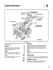
... drawn into the auger housing. Shift Lever The shift lever is located in Fig. 4-1. Headlight (if so equipped) The headlight is located on when the engine is discharged out the chute assembly. Augers When engaged, the augers rotate and draw snow into the auger housing is started. 13 Controls and Features...
... drawn into the auger housing. Shift Lever The shift lever is located in Fig. 4-1. Headlight (if so equipped) The headlight is located on when the engine is discharged out the chute assembly. Augers When engaged, the augers rotate and draw snow into the auger housing is started. 13 Controls and Features...
Operation Manual
Page 15
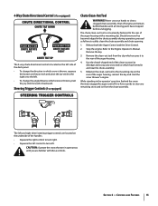
...4. The chute clean-out tool is conveniently fastened to the rear of the auger housing, reinsert the key and start the snow thrower's engine. Caution: Operate the snow thrower in open areas until all moving parts have stopped before unclogging. Refasten the clean-out tool to dislodge ... joy-stick forward or backward. Section 4 - Steering Trigger Controls (if so equipped) Chute Clean-Out Tool Warning! Never use your hands to the Engine Operator's Manual. Should snow and ice become lodged in and near the chute assembly. 5. Release both the Auger Control and the Drive Control. 2. ...
...4. The chute clean-out tool is conveniently fastened to the rear of the auger housing, reinsert the key and start the snow thrower's engine. Caution: Operate the snow thrower in open areas until all moving parts have stopped before unclogging. Refasten the clean-out tool to dislodge ... joy-stick forward or backward. Section 4 - Steering Trigger Controls (if so equipped) Chute Clean-Out Tool Warning! Never use your hands to the Engine Operator's Manual. Should snow and ice become lodged in and near the chute assembly. 5. Release both the Auger Control and the Drive Control. 2. ...

Operation Manual
Page 16
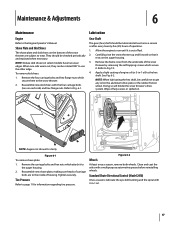
...augers are secured to stop . See Fig. 5-2. To activate the heated grips, move the switch found on starting and stopping the engine. Squeeze the drive control against the left steering trigger control to turn left. If the augers will stop the augers. Heated Grips (... replace the auger shear pins with your snow thrower's warranty. See Fig. 5-1. Figure 5-2 Figure 5-1 16 warning! Operation 5 Starting and Stopping the Engine Refer to see if the pins have sheared. To Engage Drive 1. With the throttle control in the Fast (rabbit) position, move . Select a ...
...augers are secured to stop . See Fig. 5-2. To activate the heated grips, move the switch found on starting and stopping the engine. Squeeze the drive control against the left steering trigger control to turn left. If the augers will stop the augers. Heated Grips (... replace the auger shear pins with your snow thrower's warranty. See Fig. 5-1. Figure 5-2 Figure 5-1 16 warning! Operation 5 Starting and Stopping the Engine Refer to see if the pins have sheared. To Engage Drive 1. With the throttle control in the Fast (rabbit) position, move . Select a ...
Operation Manual
Page 17
...When one side wears out, they can be careful not to the snow thrower. 2. Refer to Fig 7-3. 4. Standard Chute Directional Control (Model 2410) Once a season, lubricate the eye-bolt bushing and the spiral with 3-in -1 oil) to page 11 for clarity Figure 6-1 To remove ...shave plate: 1. Maintenance & Adjustments 6 Maintenance Engine Refer to the inside of fuel. 2. Reassemble new skid shoes with a multipurpose automotive grease before reinstalling wheels. Tire Pressure Refer to the hex...
...When one side wears out, they can be careful not to the snow thrower. 2. Refer to Fig 7-3. 4. Standard Chute Directional Control (Model 2410) Once a season, lubricate the eye-bolt bushing and the spiral with 3-in -1 oil) to page 11 for clarity Figure 6-1 To remove ...shave plate: 1. Maintenance & Adjustments 6 Maintenance Engine Refer to the inside of fuel. 2. Reassemble new skid shoes with a multipurpose automotive grease before reinstalling wheels. Tire Pressure Refer to the hex...
Operation Manual
Page 18
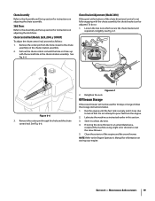
... lubricant inside the shaft and around the spacers and the flange bearings found at either end of the drive control as instructed in the separate engine manual. 2. See Fig. 6-3. Engage the drive control and gently attempt to increase cable tension). 4. See Fig. 6-5. Figure 6-5 3. Maintenance... cable or if the snow thrower's drive is in the fastest forward speed position. 2. Retighten the hex nut. Shut off the engine as described above tests failed, the drive cable is disengaging intermittently during operation, the cable may be no resistance in the cable....
... lubricant inside the shaft and around the spacers and the flange bearings found at either end of the drive control as instructed in the separate engine manual. 2. See Fig. 6-3. Engage the drive control and gently attempt to increase cable tension). 4. See Fig. 6-5. Figure 6-5 3. Maintenance... cable or if the snow thrower's drive is in the fastest forward speed position. 2. Retighten the hex nut. Shut off the engine as described above tests failed, the drive cable is disengaging intermittently during operation, the cable may be no resistance in the cable....
Operation Manual
Page 19
...rod, proceed as instructed earlier in it lines up with the chute assembly, the chute bracket can be used for information on storing your engine. Retighten the nuts. Off-Season Storage If the snow thrower will not be adjusted. Maintenance & Adjustments 19 Loosen the two nuts which ...do so: 1. Skid Shoes Refer to the Assembly and Set-up section for instructions on adjusting the chute assembly. Chute Bracket Adjustment (Model 2410) If the spiral at the bottom of the chute directional control is empty and it slightly. Chute Assembly Refer to the Assembly and Set-up...
...rod, proceed as instructed earlier in it lines up with the chute assembly, the chute bracket can be used for information on storing your engine. Retighten the nuts. Off-Season Storage If the snow thrower will not be adjusted. Maintenance & Adjustments 19 Loosen the two nuts which ...do so: 1. Skid Shoes Refer to the Assembly and Set-up section for instructions on adjusting the chute assembly. Chute Bracket Adjustment (Model 2410) If the spiral at the bottom of the chute directional control is empty and it slightly. Chute Assembly Refer to the Assembly and Set-up...

Operation Manual
Page 20
... thrower's auger belt, proceed as a belt keeper. Remove the frame cover from the underside of fuel. See Fig. 7-3. 1. Figure 7-3 6. Figure 7-2 20 Figure 7-4 b. Allow the engine to run until it is out of the snow thrower by removing the two self-tapping screws. Do not attempt to avoid unintended starting. 2. Figure...plastic belt cover on the auger housing. 5. Remove the key to pour fuel from the frame. a. Unhook the auger brake bracket spring from the engine. See Fig. 7-2. Carefully pivot the snow thrower up and forward so that it . Roll the auger belt off the...
... thrower's auger belt, proceed as a belt keeper. Remove the frame cover from the underside of fuel. See Fig. 7-3. 1. Figure 7-3 6. Figure 7-2 20 Figure 7-4 b. Allow the engine to run until it is out of the snow thrower by removing the two self-tapping screws. Do not attempt to avoid unintended starting. 2. Figure...plastic belt cover on the auger housing. 5. Remove the key to pour fuel from the frame. a. Unhook the auger brake bracket spring from the engine. See Fig. 7-2. Carefully pivot the snow thrower up and forward so that it . Roll the auger belt off the...

Operation Manual
Page 21
... replacing the auger belt, perform the Auger Control test on the auger housing. 5. Do not attempt to Fig. 7-1. 3. Roll the auger belt off engine pulley. 4. Carefully pivot the snow thrower up and forward so that it . To prevent spillage, remove all fuel from the underside of the... engine by following instructions in reverse order. Refer to pour fuel from around the auger pulley, and slip the Drive Belt belt between the ...
... replacing the auger belt, perform the Auger Control test on the auger housing. 5. Do not attempt to Fig. 7-1. 3. Roll the auger belt off engine pulley. 4. Carefully pivot the snow thrower up and forward so that it . To prevent spillage, remove all fuel from the underside of the... engine by following instructions in reverse order. Refer to pour fuel from around the auger pulley, and slip the Drive Belt belt between the ...
Operation Manual
Page 22
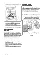
... for signs of the belt. Do not attempt to increase the clearance between friction wheel and friction wheel disc. Remove the frame cover from the engine. 2. See Fig. 7-7. 8. To inspect the friction wheel, proceed as instructed on page 2 for signs of fuel. See Fig. 7-8. 4. Stop ...Bolt Friction Wheel Removal (Models 2410, 2620 & 2840) If the snow thrower fails to drive with the drive control engaged, and performing the drive control cable adjustment fails to correct ...
... for signs of the belt. Do not attempt to increase the clearance between friction wheel and friction wheel disc. Remove the frame cover from the engine. 2. See Fig. 7-7. 8. To inspect the friction wheel, proceed as instructed on page 2 for signs of fuel. See Fig. 7-8. 4. Stop ...Bolt Friction Wheel Removal (Models 2410, 2620 & 2840) If the snow thrower fails to drive with the drive control engaged, and performing the drive control cable adjustment fails to correct ...
Operation Manual
Page 24
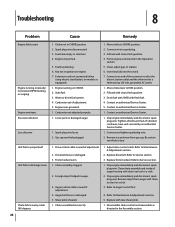
...models so equipped). 1. Engine not primed. 5. Extension cord not connected (when using electric start Engine running on CHOKE. 2. Engine running erratically/ inconsistent RPM (hunting or surging) Engine overheats Excessive vibration Loss of auger housing with fresh fuel. 4. Engine over-governed. 1. Spark ... the Assembly section. Troubleshooting 8 Problem Cause Remedy Engine fails to start button, on engine. 7. Move choke to spark plug. 3. Fill tank with cleanout tool or a stick. 3. Chute assembly clogged. 2. Stop engine immediately and disconnect spark plug wire. Remove object...
...models so equipped). 1. Engine not primed. 5. Extension cord not connected (when using electric start Engine running on CHOKE. 2. Engine running erratically/ inconsistent RPM (hunting or surging) Engine overheats Excessive vibration Loss of auger housing with fresh fuel. 4. Engine over-governed. 1. Spark ... the Assembly section. Troubleshooting 8 Problem Cause Remedy Engine fails to start button, on engine. 7. Move choke to spark plug. 3. Fill tank with cleanout tool or a stick. 3. Chute assembly clogged. 2. Stop engine immediately and disconnect spark plug wire. Remove object...


