Operation Manual
Page 2
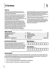
...the machine, carefully follow the recommended safety practices at (800) 828-5500 or (330) 558-7220 ◊ Write to Troy-Bilt LLC • P.O. Troy-Bilt's Customer Support telephone numbers, website address and mailing address can be found on the web at www.troybilt.com ◊ Call... this manual may cover a range of Contents Safe Operation Practices 3 Assembly & Set-Up 7 Controls 13 Operation 16 Maintenance & Adjustment 17 Service 20 Troubleshooting 24 Replacement Parts 25 Attachments 26 Warranty Back Cover Record Product Information Before setting up , operate and maintain ...
...the machine, carefully follow the recommended safety practices at (800) 828-5500 or (330) 558-7220 ◊ Write to Troy-Bilt LLC • P.O. Troy-Bilt's Customer Support telephone numbers, website address and mailing address can be found on the web at www.troybilt.com ◊ Call... this manual may cover a range of Contents Safe Operation Practices 3 Assembly & Set-Up 7 Controls 13 Operation 16 Maintenance & Adjustment 17 Service 20 Troubleshooting 24 Replacement Parts 25 Attachments 26 Warranty Back Cover Record Product Information Before setting up , operate and maintain ...
Operation Manual
Page 3
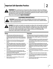
...discharge of the operator can result in serious injury. Always wear safety glasses or eye shields during operation and while performing an adjustment or repair to protect your snow-throwing pattern to clear snow. 3 Do not operate without proper instruction. 5. Disengage all ..., could result in reverse. Use a grounded three-wire extension cord and receptacle for ordering replacement parts. 2. Let engine and machine adjust to outdoor temperature before attempting to operate this machine. As with these instructions may result in operation. This machine is in personal injury...
...discharge of the operator can result in serious injury. Always wear safety glasses or eye shields during operation and while performing an adjustment or repair to protect your snow-throwing pattern to clear snow. 3 Do not operate without proper instruction. 5. Disengage all ..., could result in reverse. Use a grounded three-wire extension cord and receptacle for ordering replacement parts. 2. Let engine and machine adjust to outdoor temperature before attempting to operate this machine. As with these instructions may result in operation. This machine is in personal injury...
Operation Manual
Page 4
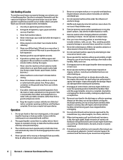
... damaged chute assembly. Stay alert for released. Never over fill fuel tank. Never operate machine at least two minutes before refueling. storing. 16. Repair any adjustments, or inspections. m. Always use . (e.g. Shut off the engine and equipment. Use only attachments and accessories approved by a ricochet. 11. Rapid retraction of starter cord (kickback...
... damaged chute assembly. Stay alert for released. Never over fill fuel tank. Never operate machine at least two minutes before refueling. storing. 16. Repair any adjustments, or inspections. m. Always use . (e.g. Shut off the engine and equipment. Use only attachments and accessories approved by a ricochet. 11. Rapid retraction of starter cord (kickback...
Operation Manual
Page 5
... to do so can lead to a runaway engine and cause it should not be used , it to operate at frequent intervals to the adjustment section in this manual. 2. Notice Regarding Emissions Engines which do not modify engine in safe working condition. Section 2 - Check their proper ... with snow throwers. to the operator's manual for cracks or leaks. Spark Arrestor Warning! Other states may lead to the maintenance and adjustment sections of engine governor. Maintenance & Storage 1. Never store the machine or fuel container inside the discharge chute is the most common cause...
... to do so can lead to a runaway engine and cause it should not be used , it to operate at frequent intervals to the adjustment section in this manual. 2. Notice Regarding Emissions Engines which do not modify engine in safe working condition. Section 2 - Check their proper ... with snow throwers. to the operator's manual for cracks or leaks. Spark Arrestor Warning! Other states may lead to the maintenance and adjustment sections of engine governor. Maintenance & Storage 1. Never store the machine or fuel container inside the discharge chute is the most common cause...
Operation Manual
Page 8
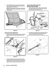
... See Fig. 3-4. Insert the end of the chute directional control. Close the flange keepers to secure the chute assembly to Chute Bracket Adjustment on Page 19. 8 Section 3- Remove cotter pin, wing nut and hex screw from chute support bracket. Push rod as possible,...See Fig. 3-6. Chute Control Head Chute Support Bracket Chute Chute Base Figure 3-4 Figure 3-6 Chute Directional Control (Model 2410) 2. See Fig. 3-7. If necessary, the lower bracket can be adjusted. Chute Assembly and Directional Control (Models 2620, 2840 and 3090XP) 1. See Fig. 3-5. 2. Remove clevis pin ...
... See Fig. 3-4. Insert the end of the chute directional control. Close the flange keepers to secure the chute assembly to Chute Bracket Adjustment on Page 19. 8 Section 3- Remove cotter pin, wing nut and hex screw from chute support bracket. Push rod as possible,...See Fig. 3-6. Chute Control Head Chute Support Bracket Chute Chute Base Figure 3-4 Figure 3-6 Chute Directional Control (Model 2410) 2. See Fig. 3-7. If necessary, the lower bracket can be adjusted. Chute Assembly and Directional Control (Models 2620, 2840 and 3090XP) 1. See Fig. 3-5. 2. Remove clevis pin ...
Operation Manual
Page 10
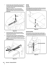
... chute support bracket with a mounting clip and a cable tie at the factory. 7. NOTE: The second hole is fastened to page 19 for Chute Control Rod adjustments. Set-Up Shear Pins A pair of the auger housing with wing nut, clevis pin, and bow-tie cotter pin removed in step 1. See Fig. 3-14...
... chute support bracket with a mounting clip and a cable tie at the factory. 7. NOTE: The second hole is fastened to page 19 for Chute Control Rod adjustments. Set-Up Shear Pins A pair of the auger housing with wing nut, clevis pin, and bow-tie cotter pin removed in step 1. See Fig. 3-14...
Operation Manual
Page 11
... chute upward or downward before operating the snow thrower. The tires are adjusted upward at all times. Caution: It is not recommended that you choose to operating the snow thrower. Chute Assembly (Models 2410 and 2620) NOTE: The upper chute on a gravel surface, keep the...2. Retighten nuts and bolts securely. Figure 3-16 Section 3 - Assembly & Set-Up 11 Check the tire pressure before retightening the wing knob. Adjustments Skid Shoes The snow thrower skid shoes are over-inflated for recommended pressure. See Fig. 4-1. Stop the engine. Loosen the four hex nuts (two...
... chute upward or downward before operating the snow thrower. The tires are adjusted upward at all times. Caution: It is not recommended that you choose to operating the snow thrower. Chute Assembly (Models 2410 and 2620) NOTE: The upper chute on a gravel surface, keep the...2. Retighten nuts and bolts securely. Figure 3-16 Section 3 - Assembly & Set-Up 11 Check the tire pressure before retightening the wing knob. Adjustments Skid Shoes The snow thrower skid shoes are over-inflated for recommended pressure. See Fig. 4-1. Stop the engine. Loosen the four hex nuts (two...

Operation Manual
Page 12
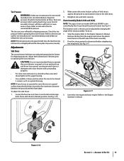
...instructions below. Position the bracket upward to provide more slack (or downward to verify your snow thrower, carefully read and follow all adjustments to increase cable tension). 9. Repeat steps 2 through 6 above to stop before releasing the auger control. Wait for approximately ten (10)...ANY signs of the machine. 6. Prior to the front of rotating, immediately return to remain engaged for ALL moving parts to verify proper adjustment has been achieved. 12 Section 3- With the throttle control in the FAST (rabbit) position and the auger control in the disengaged "...
...instructions below. Position the bracket upward to provide more slack (or downward to verify your snow thrower, carefully read and follow all adjustments to increase cable tension). 9. Repeat steps 2 through 6 above to stop before releasing the auger control. Wait for approximately ten (10)...ANY signs of the machine. 6. Prior to the front of rotating, immediately return to remain engaged for ALL moving parts to verify proper adjustment has been achieved. 12 Section 3- With the throttle control in the FAST (rabbit) position and the auger control in the disengaged "...
Operation Manual
Page 13
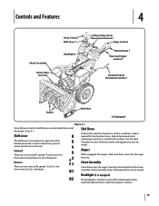
.... Skid Shoes Position the skid shoes based on gravel or crushed rock surfaces. One (1) is the slower and two (2) is discharged out the chute assembly. Adjust downward when operating on surface conditions. Augers When engaged, the augers rotate and draw snow into the auger housing is the faster. Chute assembly styles... the handle panel and is automatically turned on when the engine is the fastest. Position one (1) is the slowest and position six (6) is started. 13 Adjust upward for hard-packed snow.
.... Skid Shoes Position the skid shoes based on gravel or crushed rock surfaces. One (1) is the slower and two (2) is discharged out the chute assembly. Adjust downward when operating on surface conditions. Augers When engaged, the augers rotate and draw snow into the auger housing is the faster. Chute assembly styles... the handle panel and is automatically turned on when the engine is the fastest. Position one (1) is the slowest and position six (6) is started. 13 Adjust upward for hard-packed snow.
Operation Manual
Page 17
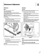
...out of engine oil (or 3-in -1 oil. 17 Tighten securely. Allow the engine to the hex shaft. Standard Chute Directional Control (Model 2410) Once a season, lubricate the eye-bolt bushing and the spiral with 3-in -1 oil) to run until it to the Engine Operator's ...: When lubricating the hex shaft, be rotated 180° to wear. Figure 6-2 Wheels At least once a season, remove both wheels. Maintenance & Adjustments 6 Maintenance Engine Refer to the auger housing. 2. To remove skid shoes: 1. Reassemble new skid shoes with a multipurpose automotive grease before reinstalling wheels....
...out of engine oil (or 3-in -1 oil. 17 Tighten securely. Allow the engine to the hex shaft. Standard Chute Directional Control (Model 2410) Once a season, lubricate the eye-bolt bushing and the spiral with 3-in -1 oil) to run until it to the Engine Operator's ...: When lubricating the hex shaft, be rotated 180° to wear. Figure 6-2 Wheels At least once a season, remove both wheels. Maintenance & Adjustments 6 Maintenance Engine Refer to the auger housing. 2. To remove skid shoes: 1. Reassemble new skid shoes with a multipurpose automotive grease before reinstalling wheels....
Operation Manual
Page 18
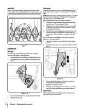
...With the drive control released, move the shift lever back and forth between the R2 position and the F6 position several times. Adjustments Figure 6-3 Drive Control When the drive control is disengaging intermittently during operation, the cable may be no resistance in the disengaged ...the above to take up " position, the cable should not turn. Proceed as follows: 1. Figure 6-5 3. Retighten the hex nut. Maintenance & Adjustments Engage the drive control and gently attempt to increase cable tension). 4. Place the shift lever in the cable. 4. See Fig. 6-4. Auger Shaft At...
...With the drive control released, move the shift lever back and forth between the R2 position and the F6 position several times. Adjustments Figure 6-3 Drive Control When the drive control is disengaging intermittently during operation, the cable may be no resistance in the disengaged ...the above to take up " position, the cable should not turn. Proceed as follows: 1. Figure 6-5 3. Retighten the hex nut. Maintenance & Adjustments Engage the drive control and gently attempt to increase cable tension). 4. Place the shift lever in the cable. 4. See Fig. 6-4. Auger Shaft At...
Operation Manual
Page 19
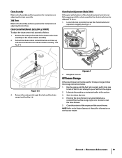
...out the chute control rod until the fuel tank is not fully engaging with the second hole in a clean, dry area. 4. Chute Bracket Adjustment (Model 2410) If the spiral at the bottom of the chute directional control is empty and it stops due to lack of the engine and the snow ... in this hole and the chute control rod. Remove the cotter pin from the engine. 2. See Fig. 6-7. Clean the exterior of fuel. Maintenance & Adjustments 19 Skid Shoes Refer to the Assembly and Set-up section for 30 days or longer, follow the storage instructions below. 1. Chute Control Rod (Models...
...out the chute control rod until the fuel tank is not fully engaging with the second hole in a clean, dry area. 4. Chute Bracket Adjustment (Model 2410) If the spiral at the bottom of the chute directional control is empty and it stops due to lack of the engine and the snow ... in this hole and the chute control rod. Remove the cotter pin from the engine. 2. See Fig. 6-7. Clean the exterior of fuel. Maintenance & Adjustments 19 Skid Shoes Refer to the Assembly and Set-up section for 30 days or longer, follow the storage instructions below. 1. Chute Control Rod (Models...

Operation Manual
Page 21
... front of the snow thrower by running engine until it stops. Lift the drive belt off the engine pulley. Refer to verify the belt is adjusted correctly. c. Replace the auger belt by removing the two self-tapping screws. Section 7 - Carefully pivot the snow thrower up and forward so that it . Remove...
... front of the snow thrower by running engine until it stops. Lift the drive belt off the engine pulley. Refer to verify the belt is adjusted correctly. c. Replace the auger belt by removing the two self-tapping screws. Section 7 - Carefully pivot the snow thrower up and forward so that it . Remove...
Operation Manual
Page 22
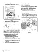
... Remove the frame cover from the engine. 2. Stop Bolt Friction Wheel Removal (Models 2410, 2620 & 2840) If the snow thrower fails to drive with the drive control engaged, and performing the drive control cable adjustment fails to correct the problem, the friction wheel may need to be removed in order...Friction Wheel Inspection (Model 3090XP) If the snow thrower fails to drive with the drive control engaged, and performing the drive control cable adjustment fails to correct the problem, the friction wheel may need to run until it is out of the snow thrower by removing the screw ...
... Remove the frame cover from the engine. 2. Stop Bolt Friction Wheel Removal (Models 2410, 2620 & 2840) If the snow thrower fails to drive with the drive control engaged, and performing the drive control cable adjustment fails to correct the problem, the friction wheel may need to be removed in order...Friction Wheel Inspection (Model 3090XP) If the snow thrower fails to drive with the drive control engaged, and performing the drive control cable adjustment fails to correct the problem, the friction wheel may need to run until it is out of the snow thrower by removing the screw ...
Operation Manual
Page 23
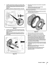
Perform the Drive Control test on page 18 in the Maintenance and Adjustments section. See Fig. 7-10. Reassemble the side plates with the next screw. Figure 7-10 Section 7 - See Fig. 7-11. Remove the rubber ring from the right ... friction wheel's side plates together. NOTE: When reassembling the friction wheel assembly, make sure that the rubber ring is in place in the Maintenance and Adjustments section.
Perform the Drive Control test on page 18 in the Maintenance and Adjustments section. See Fig. 7-10. Reassemble the side plates with the next screw. Figure 7-10 Section 7 - See Fig. 7-11. Remove the rubber ring from the right ... friction wheel's side plates together. NOTE: When reassembling the friction wheel assembly, make sure that the rubber ring is in place in the Maintenance and Adjustments section.
Operation Manual
Page 24
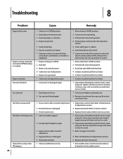
...Drive belt loose or damaged. 3. Auger control cable in ignition on engine. 7. Replace drive belt. Replace friction wheel. Refer to Maintenance & Adjustments section. 5. Replace with clean-out tool or a stick. 2. Spark plug wire disconnected. 3. Key not in need of power Unit fails to... so equipped). 1. Chute assembly clogged. 2. Shear pin(s) sheared. 1. Insert key fully into the switch. 7. Friction wheel worn. 1. Adjust drive control cable. Engine not primed. 5. Stale fuel. 3. Water or dirt in need of auger housing with new shear pin(s). 1. Move choke...
...Drive belt loose or damaged. 3. Auger control cable in ignition on engine. 7. Replace drive belt. Replace friction wheel. Refer to Maintenance & Adjustments section. 5. Replace with clean-out tool or a stick. 2. Spark plug wire disconnected. 3. Key not in need of power Unit fails to... so equipped). 1. Chute assembly clogged. 2. Shear pin(s) sheared. 1. Insert key fully into the switch. 7. Friction wheel worn. 1. Adjust drive control cable. Engine not primed. 5. Stale fuel. 3. Water or dirt in need of auger housing with new shear pin(s). 1. Move choke...
Operation Manual
Page 28
...replace a warranted product. This limited warranty does not provide coverage in your Yellow Pages, or contact Troy-Bilt LLC at www.troybilt.com. f. Troy-Bilt shall not be defective in materials or workmanship. Some states do not allow the exclusion or limitation of...WITH PROOF OF PURCHASE, through Troy-Bilt's authorized channels of the product as described below is repair or replacement of export distribution. Routine maintenance items such as lubricants, filters, blade sharpening, tune-ups, brake adjustments, clutch adjustments, deck adjustments, and normal deterioration of the ...
...replace a warranted product. This limited warranty does not provide coverage in your Yellow Pages, or contact Troy-Bilt LLC at www.troybilt.com. f. Troy-Bilt shall not be defective in materials or workmanship. Some states do not allow the exclusion or limitation of...WITH PROOF OF PURCHASE, through Troy-Bilt's authorized channels of the product as described below is repair or replacement of export distribution. Routine maintenance items such as lubricants, filters, blade sharpening, tune-ups, brake adjustments, clutch adjustments, deck adjustments, and normal deterioration of the ...


