
Operation Manual
Page 17
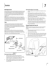
...8260;8-16 ) that attach a single tine to Fig. 7-1 for ordering information. Hex Screw Front/Forward Hex Screw Flange Lock Nut Hex Lock Nut Figure 7-1 Removing/Installing a Single Tine 1. Rear/Operator Removing/Installing a Tine Assembly: 1. Lightly file or sand, ...as a complete set. With the engine shut off the shaft. 3. If removing both tine assemblies, mark them "left side of each tine assembly so that its cutting edge (sharp) will enter the soil first when the tiller...
...8260;8-16 ) that attach a single tine to Fig. 7-1 for ordering information. Hex Screw Front/Forward Hex Screw Flange Lock Nut Hex Lock Nut Figure 7-1 Removing/Installing a Single Tine 1. Rear/Operator Removing/Installing a Tine Assembly: 1. Lightly file or sand, ...as a complete set. With the engine shut off the shaft. 3. If removing both tine assemblies, mark them "left side of each tine assembly so that its cutting edge (sharp) will enter the soil first when the tiller...
Service Manual
Page 5
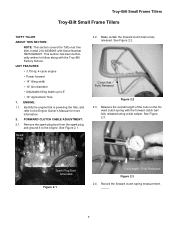
... Engine Owner's Manual for - See Figure 2.1. See Figure 2.2. Fully Released Figure 2.3 2.4. FORWARD CLUTCH CABLE ADJUSTMENT: 2.1. Clutch Bail Fully Released Figure 2.2 2.3. Troy-Bilt Small Frame Tillers Troy-Bilt Small Frame Tillers TUFFY TILLER ABOUT THIS SECTION: NOTE: This section covers the Tuffy rear tine tiller, model 21A-630B063 with Serial Number 1B212G80447. Make certain the forward clutch bail is powering the...
... Engine Owner's Manual for - See Figure 2.1. See Figure 2.2. Fully Released Figure 2.3 2.4. FORWARD CLUTCH CABLE ADJUSTMENT: 2.1. Clutch Bail Fully Released Figure 2.2 2.3. Troy-Bilt Small Frame Tillers Troy-Bilt Small Frame Tillers TUFFY TILLER ABOUT THIS SECTION: NOTE: This section covers the Tuffy rear tine tiller, model 21A-630B063 with Serial Number 1B212G80447. Make certain the forward clutch bail is powering the...
Service Manual
Page 15
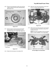
Hex Screws and Lock Nuts Left and Right Tine Assemblies 11 See Figure 6.30. Raise the rear of the tine assemblies for correct installation. See Figure 6.31. Remove the transmission pulley, key and front support washer from the drive shaft assembly....Hex Screw Figure 6.30 6.31. Remove the hex screws and lock nuts securing the right and left tine assemblies using a 1/2" socket. See Figure 6.33. Transmission Pulley Key Belleville Troy-Bilt Small Frame Tillers 6.33. Remove the hex screw securing the forward idler assembly to the transmission housing assembly using a 9/...
Hex Screws and Lock Nuts Left and Right Tine Assemblies 11 See Figure 6.30. Raise the rear of the tine assemblies for correct installation. See Figure 6.31. Remove the transmission pulley, key and front support washer from the drive shaft assembly....Hex Screw Figure 6.30 6.31. Remove the hex screws and lock nuts securing the right and left tine assemblies using a 1/2" socket. See Figure 6.33. Transmission Pulley Key Belleville Troy-Bilt Small Frame Tillers 6.33. Remove the hex screw securing the forward idler assembly to the transmission housing assembly using a 9/...
Service Manual
Page 17
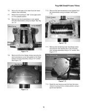
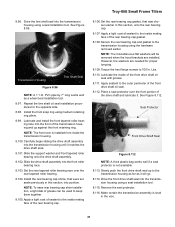
...oil to the transmission housing assembly using a punch and hammer. 13 Remove the remaining lower hex flange screw securing the rear bearing cap to drain from the transmission using a scraper. Remove the front transmission cover gasket from the transmission case ...Cover Gasket Troy-Bilt Small Frame Tillers 7.10. Cover Gasket Tine Worm Figure 7.8 7.9. Rear Bearing Cap Transmission Overlap Point Rear Transmission Cover Figure 7.9 Short Hex Flange Screw Figure 7.11 7.12. Break the rear bearing cap free from the transmission using a 1/2" socket. Remove the rear transmission cover ...
...oil to the transmission housing assembly using a punch and hammer. 13 Remove the remaining lower hex flange screw securing the rear bearing cap to drain from the transmission using a scraper. Remove the front transmission cover gasket from the transmission case ...Cover Gasket Troy-Bilt Small Frame Tillers 7.10. Cover Gasket Tine Worm Figure 7.8 7.9. Rear Bearing Cap Transmission Overlap Point Rear Transmission Cover Figure 7.9 Short Hex Flange Screw Figure 7.11 7.12. Break the rear bearing cap free from the transmission using a 1/2" socket. Remove the rear transmission cover ...
Service Manual
Page 35
...housing until it . Lubricate and install the front tapered roller bearing race into position. Secure the rear bearing cap and gasket to 100 In. Troy-Bilt Small Frame Tillers 8.96. See Figure 8.96. Carefully begin sliding the drive shaft assembly into the transmission housing ... race. 8.103. Torque the hex flange screws to the transmission housing using a seal installation tool. 8.115. Lbs. 8.110. Transmission Housing Tine Shaft Seal Figure 8.96 NOTE: A 1" I.D. Slide the drive shaft assembly into the transmission housing using medium retaining ring pliers. 8.99. ...
...housing until it . Lubricate and install the front tapered roller bearing race into position. Secure the rear bearing cap and gasket to 100 In. Troy-Bilt Small Frame Tillers 8.96. See Figure 8.96. Carefully begin sliding the drive shaft assembly into the transmission housing ... race. 8.103. Torque the hex flange screws to the transmission housing using a seal installation tool. 8.115. Lbs. 8.110. Transmission Housing Tine Shaft Seal Figure 8.96 NOTE: A 1" I.D. Slide the drive shaft assembly into the transmission housing using medium retaining ring pliers. 8.99. ...


