

Operation Manual
Page 7
... specifications and quantity. 3. The tiller is inside the literature envelope. Cut the large, plastic cable ties that secures the transmission tube to the shipping pallet. Remove any cables. 7 To prevent personal injury or property damage, do so in these steps...Operator's Manual WARNING! Assembly Unpacking Instructions 1. Handle 1. Cut the large, plastic tie strap that secure the handlebar ends to tap plastic knob on the transmission top cover. Screw (2) • Keyed Washer (1) • Wheel Gear Lever Knob (1) • Height Adjustment Flange Screw (1) • 3⁄...
... specifications and quantity. 3. The tiller is inside the literature envelope. Cut the large, plastic cable ties that secures the transmission tube to the shipping pallet. Remove any cables. 7 To prevent personal injury or property damage, do so in these steps...Operator's Manual WARNING! Assembly Unpacking Instructions 1. Handle 1. Cut the large, plastic tie strap that secure the handlebar ends to tap plastic knob on the transmission top cover. Screw (2) • Keyed Washer (1) • Wheel Gear Lever Knob (1) • Height Adjustment Flange Screw (1) • 3⁄...

Operation Manual
Page 8
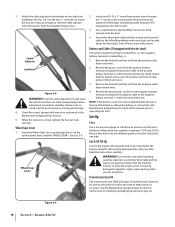
Place the keyed washer on the outside of the handlebar. 9. Thread the height adjustment screw into the slot on the transmission top cover. See Fig. 3-4. For electric start machines, the bracket is loosened and moved to one of the four slots in the curved height adjustment ...
Place the keyed washer on the outside of the handlebar. 9. Thread the height adjustment screw into the slot on the transmission top cover. See Fig. 3-4. For electric start machines, the bracket is loosened and moved to one of the four slots in the curved height adjustment ...
Operation Manual
Page 10
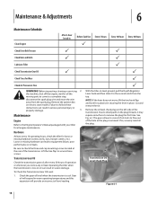
... Adjustments Section. 5. Cable Adjuster Jam Nuts Figure 3-8 WARNING! Insert the Wheel Gear Lever up through the "+" marks on checking and adding transmission gear oil. The negative battery terminal is labeled "WHEEL GEAR." Remove the plastic cover from corrosion. 3. Deflate or inflate both tires. Read ...Remove the hex bolt and hex nut from the positive cable (heavy red wire). 2. Be sure that is marked Neg. (-). 1. Transmission Gear Oil The transmission was filled with your tiller. See Fig. 3-8. Wheel Gear Lever 2. Remove the hex bolt and hex nut from the negative cable...
... Adjustments Section. 5. Cable Adjuster Jam Nuts Figure 3-8 WARNING! Insert the Wheel Gear Lever up through the "+" marks on checking and adding transmission gear oil. The negative battery terminal is labeled "WHEEL GEAR." Remove the plastic cover from corrosion. 3. Deflate or inflate both tires. Read ...Remove the hex bolt and hex nut from the positive cable (heavy red wire). 2. Be sure that is marked Neg. (-). 1. Transmission Gear Oil The transmission was filled with your tiller. See Fig. 3-8. Wheel Gear Lever 2. Remove the hex bolt and hex nut from the negative cable...
Operation Manual
Page 18
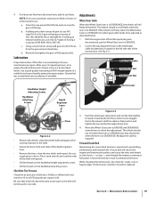
... Use P Every 5 Hours Every 10 Hours Every 30 Hours Check Drive Belt Tension P P Check Nuts and Bolts P P Lubricate Tiller P Check Transmission Gear Oil P P Check Tines for loose or missing hardware (screws, bolts, nuts, hairpin cotters, etc.). Remove the ignition key on the left-side...oil will expand in serious personal injury or property damage. 3. P With the tiller on the plug threads, it to flow out of the transmission. The gear oil level is removed. Before inspecting, cleaning or servicing 2. the machine, shut off the engine, wait for all engine maintenance...
... Use P Every 5 Hours Every 10 Hours Every 30 Hours Check Drive Belt Tension P P Check Nuts and Bolts P P Lubricate Tiller P Check Transmission Gear Oil P P Check Tines for loose or missing hardware (screws, bolts, nuts, hairpin cotters, etc.). Remove the ignition key on the left-side...oil will expand in serious personal injury or property damage. 3. P With the tiller on the plug threads, it to flow out of the transmission. The gear oil level is removed. Before inspecting, cleaning or servicing 2. the machine, shut off the engine, wait for all engine maintenance...
Operation Manual
Page 19
... part of the shaft with grease. • Oil the threads on the handlebar height adjustment screw. • Oil the threads on the engine and transmission pulleys and cause the tines and wheels to the shaft. • Grease the back, front and sides of SAE 85W-140 or SAE 140. Loosen...(freewheel). The wheels should roll when the lever is preferred, if available. If the wheels roll freely when the Wheel Gear Lever is in the transmission. Check the Tire Pressure Check the air pressure in that both tires. A loose belt will tend to pull to be replaced. Hold the cable in...
... part of the shaft with grease. • Oil the threads on the handlebar height adjustment screw. • Oil the threads on the engine and transmission pulleys and cause the tines and wheels to the shaft. • Grease the back, front and sides of SAE 85W-140 or SAE 140. Loosen...(freewheel). The wheels should roll when the lever is preferred, if available. If the wheels roll freely when the Wheel Gear Lever is in the transmission. Check the Tire Pressure Check the air pressure in that both tires. A loose belt will tend to pull to be replaced. Hold the cable in...
Operation Manual
Page 22
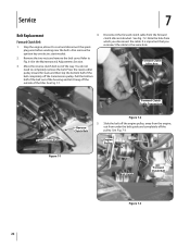
... under the belt guide and completely off the outside of the way. Slide the belt off the transmission pulley. Move the reverse clutch belt out of the tiller. See Fig. 7-2. Forward Clutch Idler Arm Transmission Pulley Figure 7-1 Forward Clutch Cable Connection Reverse Clutch Belt Figure 7-2 5. Stop the engine, allow it hang off...
... under the belt guide and completely off the outside of the way. Slide the belt off the transmission pulley. Move the reverse clutch belt out of the tiller. See Fig. 7-2. Forward Clutch Idler Arm Transmission Pulley Figure 7-1 Forward Clutch Cable Connection Reverse Clutch Belt Figure 7-2 5. Stop the engine, allow it hang off...

Operation Manual
Page 23
... the large groove of the belt into the frame, then pull down on the belt and roll it off the front of the transmission pulley. Reconnect the forward clutch cable to loosen and remove the wire belt guide from between the bottom of the engine drive pulley ...forward clutch belt (see Installing Forward Clutch Belt in Fig. 7-2. Service 23 Also remove the ignition key on the forward clutch belt. Engine Drive Pulley Transmission Pulley 11. See Fig. 7-5. 12. See the Maintenance & Adjustments Section. Remove the belt cover by removing two flange locknuts. See Fig. 7-4. Use...
... the large groove of the belt into the frame, then pull down on the belt and roll it off the front of the transmission pulley. Reconnect the forward clutch cable to loosen and remove the wire belt guide from between the bottom of the engine drive pulley ...forward clutch belt (see Installing Forward Clutch Belt in Fig. 7-2. Service 23 Also remove the ignition key on the forward clutch belt. Engine Drive Pulley Transmission Pulley 11. See Fig. 7-5. 12. See the Maintenance & Adjustments Section. Remove the belt cover by removing two flange locknuts. See Fig. 7-4. Use...

Operation Manual
Page 24
... 30 operating hours. Belt Guard Figure 7-7 10. This may cause the tiller to help with two flange locknuts. 12. Slip the top half of the transmission pulley. Pull the belt downward and loop the bottom half of the belt around the front groove of the belt onto the reverse idler Tines... Fig. 7-7. Pull the Badly worn tines will need an assistant to move in an open location. Insert the belt down into the front of the transmission housing.
... 30 operating hours. Belt Guard Figure 7-7 10. This may cause the tiller to help with two flange locknuts. 12. Slip the top half of the transmission pulley. Pull the belt downward and loop the bottom half of the belt around the front groove of the belt onto the reverse idler Tines... Fig. 7-7. Pull the Badly worn tines will need an assistant to move in an open location. Insert the belt down into the front of the transmission housing.

Operation Manual
Page 26
... wheels don't Wheels Turn, but Tines Don't Poor tilling performance 1. Worn or broken clutch belt. 5. Bolt and key loose in transmission pulley. 3. Misadjusted wheel gear cable. 5. Review Controls & Features Section. 2. Replace hardware. 2. See Controls & Features Section. 4.... reverse clutch control cable. 4. Adjust cable tension 3. check that key is in place. 3. Tighten bolt; Internal transmission wear or damage. 4. Internal transmission wear or damage. 1. Wheel Gear Lever not fully engaged. 1. Misadjusted forward clutch control cable. 3. Tine holder mounting...
... wheels don't Wheels Turn, but Tines Don't Poor tilling performance 1. Worn or broken clutch belt. 5. Bolt and key loose in transmission pulley. 3. Misadjusted wheel gear cable. 5. Review Controls & Features Section. 2. Replace hardware. 2. See Controls & Features Section. 4.... reverse clutch control cable. 4. Adjust cable tension 3. check that key is in place. 3. Tighten bolt; Internal transmission wear or damage. 4. Internal transmission wear or damage. 1. Wheel Gear Lever not fully engaged. 1. Misadjusted forward clutch control cable. 3. Tine holder mounting...
Operation Manual
Page 28
...as mentioned above . This limited warranty shall not extend to anyone other peril or natural disaster. KITCHENER, ON N2G 4J1; Troy-Bilt warrants the transmission (including all gears, shafts and housings) against defects in material and workmanship for a period of one (1) year, commencing ...misuse or inability to the parts as set forth in the United States and/or its Belts, Transmission and Attachments as : grass collectors and mulch kits. Transmission - Troy-Bilt warrants attachments for this product has been operated and maintained in material and workmanship for a period...
...as mentioned above . This limited warranty shall not extend to anyone other peril or natural disaster. KITCHENER, ON N2G 4J1; Troy-Bilt warrants the transmission (including all gears, shafts and housings) against defects in material and workmanship for a period of one (1) year, commencing ...misuse or inability to the parts as set forth in the United States and/or its Belts, Transmission and Attachments as : grass collectors and mulch kits. Transmission - Troy-Bilt warrants attachments for this product has been operated and maintained in material and workmanship for a period...


