
Operation Manual
Page 7
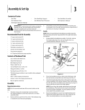
...3-1. 3. Remove all assembly steps are missing or damaged). Handle NOTE: When disassembling the handlebar assembly, keep the left -side ratchet, handlebar end, and clamp. Recommended Tools for battery terminals (2) • Keys in your local dealer or the Troy-Bilt Technical Service ...pressure gauge (1) • 4-1⁄2" high wood block to one of Carton • One Tiller • One Hardware Pack • One Engine Operator's Manual • One Handlebar Support • One Wheels/Tines PTO Lever • One Handlebar Assembly • One Operator's Manual WARNING! Assembly ...
...3-1. 3. Remove all assembly steps are missing or damaged). Handle NOTE: When disassembling the handlebar assembly, keep the left -side ratchet, handlebar end, and clamp. Recommended Tools for battery terminals (2) • Keys in your local dealer or the Troy-Bilt Technical Service ...pressure gauge (1) • 4-1⁄2" high wood block to one of Carton • One Tiller • One Hardware Pack • One Engine Operator's Manual • One Handlebar Support • One Wheels/Tines PTO Lever • One Handlebar Assembly • One Operator's Manual WARNING! Assembly ...
Operation Manual
Page 9
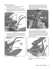
...Short Link Figure 3-6 3. Install the star washer 2. Remove the temporary screw from the forward holes inserted in the next step, insert a screw temporarily into the forward most holes of the handle. Align the rear most holes of the Wheels/Tines/PTO Lever over stretch the spring while installing. ...bushing from hardware bag. Use pliers to the right side. Remove both sets of the clutch pawl spring down into the hole in place while...
...Short Link Figure 3-6 3. Install the star washer 2. Remove the temporary screw from the forward holes inserted in the next step, insert a screw temporarily into the forward most holes of the handle. Align the rear most holes of the Wheels/Tines/PTO Lever over stretch the spring while installing. ...bushing from hardware bag. Use pliers to the right side. Remove both sets of the clutch pawl spring down into the hole in place while...
Operation Manual
Page 15
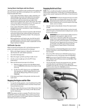
...section. When practicing, set the Depth Regulator Lever to a desired depth. 4. NOTE: Do not move the Wheels/Tines/ PTO Drive Lever down to FORWARD position. To move the tiller forward and engage the tines, squeeze and hold either Forward Interlock Lever against the handlebar grip (See Fig....These controls can also be aware that the tiller can 't roll). Figure 4-2 Section 5 - Disconnect the cables from you suspect the battery charge is weak, and there is damaged, disconnect, and remove it. With the engine running, move the Wheels/Tines/PTO Drive Lever into DISENGAGE, then ...
...section. When practicing, set the Depth Regulator Lever to a desired depth. 4. NOTE: Do not move the Wheels/Tines/ PTO Drive Lever down to FORWARD position. To move the tiller forward and engage the tines, squeeze and hold either Forward Interlock Lever against the handlebar grip (See Fig....These controls can also be aware that the tiller can 't roll). Figure 4-2 Section 5 - Disconnect the cables from you suspect the battery charge is weak, and there is damaged, disconnect, and remove it. With the engine running, move the Wheels/Tines/PTO Drive Lever into DISENGAGE, then ...
Operation Manual
Page 17
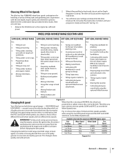
... Preparing a deep belt speed range in REVERSE, the wheels are some tips: 1. going too deep). Figure 4-5 Changing Belt speed Your tiller has two belt-driven speed ranges - To help avoid serious personal injury, stop the engine, remove the ignition key, disconnect spark plug wire and move ...the forward belt into. This change is a matter of wheel and tine speeds available when using the...
... Preparing a deep belt speed range in REVERSE, the wheels are some tips: 1. going too deep). Figure 4-5 Changing Belt speed Your tiller has two belt-driven speed ranges - To help avoid serious personal injury, stop the engine, remove the ignition key, disconnect spark plug wire and move ...the forward belt into. This change is a matter of wheel and tine speeds available when using the...

Operation Manual
Page 19
... tender. • While power composting, try to top-rear engine pulley groove. Refer to the surface. Check this won't be necessary to remove the debris by hand, stop the engine, allow all moving parts to cut away the material). Top-Rear Gear Tilling Tips & Techniques Figure ...4-9 Let the Tiller Do the Work • While tilling, relax and let the wheels pull the tiller along 4. use very shallow depth settings to prevent injury to plants whose roots often grow close to Fig...
... tender. • While power composting, try to top-rear engine pulley groove. Refer to the surface. Check this won't be necessary to remove the debris by hand, stop the engine, allow all moving parts to cut away the material). Top-Rear Gear Tilling Tips & Techniques Figure ...4-9 Let the Tiller Do the Work • While tilling, relax and let the wheels pull the tiller along 4. use very shallow depth settings to prevent injury to plants whose roots often grow close to Fig...

Operation Manual
Page 23
.... 2. Figure 4-19 Place the Wheels/Tines/PTO Drive Lever into FREE WHEEL. See Fig. 4-20. Read the controls information and operating procedures for a week or so. Swing-Out Bolts Figure 4-20 Section 5 - Dry plants are more difficult to level ground. 2. See Fig. 4-17. Removing the Tine Attachment 1. Move the tiller to till under, and...
.... 2. Figure 4-19 Place the Wheels/Tines/PTO Drive Lever into FREE WHEEL. See Fig. 4-20. Read the controls information and operating procedures for a week or so. Swing-Out Bolts Figure 4-20 Section 5 - Dry plants are more difficult to level ground. 2. See Fig. 4-17. Removing the Tine Attachment 1. Move the tiller to till under, and...
Operation Manual
Page 27
... side of petroleum jelly or grease to the tine shaft and its oil seals. 1. After cleaning away any debris and removing old grease, apply fresh grease to hardware listed below. Remove the wheels by the positive (+) cable. Failure to the tine shaft. Prop the transmission up . • After cleaning the battery and terminals... is sealed and is loose, the bolt needs tightening. Mounting Bolt Figure 6-1 Neutral Plunger Assembly Jam Nut • The jam nut is located on your tiller is visible. Maintenance & Adjustments 27
... side of petroleum jelly or grease to the tine shaft and its oil seals. 1. After cleaning away any debris and removing old grease, apply fresh grease to hardware listed below. Remove the wheels by the positive (+) cable. Failure to the tine shaft. Prop the transmission up . • After cleaning the battery and terminals... is sealed and is loose, the bolt needs tightening. Mounting Bolt Figure 6-1 Neutral Plunger Assembly Jam Nut • The jam nut is located on your tiller is visible. Maintenance & Adjustments 27

Operation Manual
Page 31
... for the Forward Interlock Safety System is in FORWARD. 1. This switch is open whenever the Wheels/ Tines/PTO Drive Lever is designed to press one of dirt, remove the build-up of the lower screws from the tiller housing cover. A broken or disconnected wire could ground out the engine's ignition. 3. Lubrication should be...
... for the Forward Interlock Safety System is in FORWARD. 1. This switch is open whenever the Wheels/ Tines/PTO Drive Lever is designed to press one of dirt, remove the build-up of the lower screws from the tiller housing cover. A broken or disconnected wire could ground out the engine's ignition. 3. Lubrication should be...
Operation Manual
Page 34
... bolt at the back of the drive lever and remove the belt adjustment tool from the operator's position behind handlebars. Adjustment.... it should be inspected after every 30 operating hours. 34 Section 6- The drive shaft then turns the wheels and tine shafts in the adjustment block firmly. 7. Maintenance & Adjustments Let go of the belt adjustment block... disc is needed. Clutch Roller Adjustment Block Figure 6-16 Figure 6-17 6. When you raise the Wheels/Tines/PTO Drive Lever up or down and the measurement between the rotating reverse disc and the transmission...
... bolt at the back of the drive lever and remove the belt adjustment tool from the operator's position behind handlebars. Adjustment.... it should be inspected after every 30 operating hours. 34 Section 6- The drive shaft then turns the wheels and tine shafts in the adjustment block firmly. 7. Maintenance & Adjustments Let go of the belt adjustment block... disc is needed. Clutch Roller Adjustment Block Figure 6-16 Figure 6-17 6. When you raise the Wheels/Tines/PTO Drive Lever up or down and the measurement between the rotating reverse disc and the transmission...
Operation Manual
Page 37
...Spark Plug 1. The correct electrode gap is felt - loose particles can enter the engine, causing damage. Do routine tiller lubrication and check for assistance. Move the Wheels/Tines/PTO Drive Lever to distribute the oil internally. Maintenance & Adjustments 37 The switch body on the bottom of... 7. Off-Season Storage When your engine manual literature. 4. When engine is equipped with a second wrench. 6. See Fig. 6-22. 10. Remove and inspect the plug every 50 operating hours or annually, whichever occurs first. Replace spark plug, but do not reconnect the plug wire. Clean ...
...Spark Plug 1. The correct electrode gap is felt - loose particles can enter the engine, causing damage. Do routine tiller lubrication and check for assistance. Move the Wheels/Tines/PTO Drive Lever to distribute the oil internally. Maintenance & Adjustments 37 The switch body on the bottom of... 7. Off-Season Storage When your engine manual literature. 4. When engine is equipped with a second wrench. 6. See Fig. 6-22. 10. Remove and inspect the plug every 50 operating hours or annually, whichever occurs first. Replace spark plug, but do not reconnect the plug wire. Clean ...
Operation Manual
Page 39
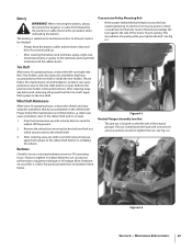
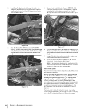
... slack is needed . 10. Avoid contacting the reverse disc. See Fig. 7-7. Place the Wheels/Tines/PTO Drive Lever in the Operation Section. 15. OIL Mounting Bolt Drive Belt Reverse Disc...8260;16"-thick board between the top of the engine pulley and the cast iron housing next to remove it in either of the grooves in Fig. 7-6. See Fig. 7-5. Remember to loosen the ...mounting bolt shown in the top pulley. 11. Move the bottom half of a screwdriver. If your tiller has a Bumper Attachment mounted, it is seated properly on the top pulley. Reverse Disc Follow these...
... slack is needed . 10. Avoid contacting the reverse disc. See Fig. 7-7. Place the Wheels/Tines/PTO Drive Lever in the Operation Section. 15. OIL Mounting Bolt Drive Belt Reverse Disc...8260;16"-thick board between the top of the engine pulley and the cast iron housing next to remove it in either of the grooves in Fig. 7-6. See Fig. 7-5. Remember to loosen the ...mounting bolt shown in the top pulley. 11. Move the bottom half of a screwdriver. If your tiller has a Bumper Attachment mounted, it is seated properly on the top pulley. Reverse Disc Follow these...
Operation Manual
Page 40
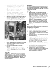
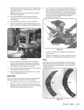
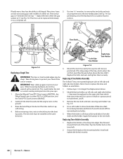
... the way the old tine was positioned. (The sharp edge of a tilled row. The tines or tine hooded edges may be replaced individually remove. Gently tilt the tiller forward until the engine rests on the tine shaft. 2. Replacing A Tine Holder Assembly The 16 Bolo Tines are mounted eight per side on... replaced on the hardware if it up with a metal tool. Here's how to till deeply. Remove the two bolts and nuts securing each holder. Move the Wheels/Tines/PTO Drive Lever to NEUTRAL, the Wheel Speed Lever to either FAST or SLOW position, and the Tines/PTO Clutch Lever to mark them...
... the way the old tine was positioned. (The sharp edge of a tilled row. The tines or tine hooded edges may be replaced individually remove. Gently tilt the tiller forward until the engine rests on the tine shaft. 2. Replacing A Tine Holder Assembly The 16 Bolo Tines are mounted eight per side on... replaced on the hardware if it up with a metal tool. Here's how to till deeply. Remove the two bolts and nuts securing each holder. Move the Wheels/Tines/PTO Drive Lever to NEUTRAL, the Wheel Speed Lever to either FAST or SLOW position, and the Tines/PTO Clutch Lever to mark them...
Technical Manual
Page 2
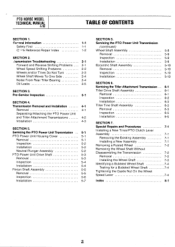
... 5-4 Pinion Shaft Assembly 5-5 Removal 5-5 Inspection 5-6 Installation 5-7 SECTION 5. PTO HORSE MODEL TECHNICAL MANUAL 4/90 TABLE OF CONTENTS SECTION 1. (zeneral Information 1-1 Safety First 1-1 C- 4-k Reference Repair Index 1-2 SECTION 2. .'ransmission Troubleshooting 2-1 Forward and Reverse Shifting Problems 2-1 Wheel Speed Shifting Problems 2-2 Wheels and/or Tines Do Not Turn 2-3 Wheel Shaft Moves To One Side 2-4 Noise From Rear Tiller Bearing 2-4 Oil Leaks...
... 5-4 Pinion Shaft Assembly 5-5 Removal 5-5 Inspection 5-6 Installation 5-7 SECTION 5. PTO HORSE MODEL TECHNICAL MANUAL 4/90 TABLE OF CONTENTS SECTION 1. (zeneral Information 1-1 Safety First 1-1 C- 4-k Reference Repair Index 1-2 SECTION 2. .'ransmission Troubleshooting 2-1 Forward and Reverse Shifting Problems 2-1 Wheel Speed Shifting Problems 2-2 Wheels and/or Tines Do Not Turn 2-3 Wheel Shaft Moves To One Side 2-4 Noise From Rear Tiller Bearing 2-4 Oil Leaks...

Technical Manual
Page 4
... an odorless and deadly poison. HANDLE PARTS CAREFULLY! PTO HORSE MODEL TECHNICAL MANUAL Page 1-2 4/90 SECTION 1: General Information...Wheels Transmission Pulley Wheel Shaft Wheel Speed Gears Wheel Speed Lever Worm, PTO Power Unit Drive Shaft Worm, Tiller Drive Shaft Worm Gear, Wheel Shaft Worm Gear, Tiller Tine Shaft TECHNICAL MANUAL OWNER/OPERATOR MANUAL If Keep sparks, flames, and cigarettes away. REPLACEMENT PARTS! approved covered metal safety container to avoid cutting yourself. Remove...this tiller. Do not run the engine in the table below. Use only genuine Troy-Bilt ...
... an odorless and deadly poison. HANDLE PARTS CAREFULLY! PTO HORSE MODEL TECHNICAL MANUAL Page 1-2 4/90 SECTION 1: General Information...Wheels Transmission Pulley Wheel Shaft Wheel Speed Gears Wheel Speed Lever Worm, PTO Power Unit Drive Shaft Worm, Tiller Drive Shaft Worm Gear, Wheel Shaft Worm Gear, Tiller Tine Shaft TECHNICAL MANUAL OWNER/OPERATOR MANUAL If Keep sparks, flames, and cigarettes away. REPLACEMENT PARTS! approved covered metal safety container to avoid cutting yourself. Remove...this tiller. Do not run the engine in the table below. Use only genuine Troy-Bilt ...
Technical Manual
Page 9
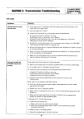
...Transmission Troubleshooting PTO HORSE MODEL TECHNICAL MANUAL Page 2-5 4/90 Oil Leaks Symptom Oil leaks from the rear of the tiller attachment housing. Oil leaks from the wheel shaft oil ...8226; Check for excessive play in the wheel shaft and replace seal. • Give new seals time to lap in the tiller tine shaft. Contact the TROY-BILT Technical Service Department for a special seal....Use emery cloth to remove any minor defects. ■ Replace the tiller tine shaft if necessary. • Check for side-to-side and vertical play in . • Inspect the wheel shaft for minor damage...
...Transmission Troubleshooting PTO HORSE MODEL TECHNICAL MANUAL Page 2-5 4/90 Oil Leaks Symptom Oil leaks from the rear of the tiller attachment housing. Oil leaks from the wheel shaft oil ...8226; Check for excessive play in the wheel shaft and replace seal. • Give new seals time to lap in the tiller tine shaft. Contact the TROY-BILT Technical Service Department for a special seal....Use emery cloth to remove any minor defects. ■ Replace the tiller tine shaft if necessary. • Check for side-to-side and vertical play in . • Inspect the wheel shaft for minor damage...

Technical Manual
Page 13
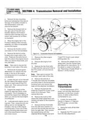
...wire that leads from the keyswitch wire harness to remove the transmission when the tiller is fully assembled. PTO HORSE MODEL SECTION 4: Transmission Removal and Installation TECHNICAL MANUAL Page 4-1 4/90 The PTO Horse Model transmission consists of the handlebar base. 2....8226;~ DOG CLUTCH/POWER UNIT 4I TRANSMISSION PULLEY DOG CLUTCH/TILLER ATTACHMENT TILLER ATTACHMENT SWINGBOLTS WHEEL SHAFT TINES/PTO CLUTCH LEVER ,07 Figure 4-1: PTO Power Unit Transmission and Tiller Attachment Transmission. 3 TILLER TINE SHAFT A DANGER The battery produces inflammable and explosive hydrogen...
...wire that leads from the keyswitch wire harness to remove the transmission when the tiller is fully assembled. PTO HORSE MODEL SECTION 4: Transmission Removal and Installation TECHNICAL MANUAL Page 4-1 4/90 The PTO Horse Model transmission consists of the handlebar base. 2....8226;~ DOG CLUTCH/POWER UNIT 4I TRANSMISSION PULLEY DOG CLUTCH/TILLER ATTACHMENT TILLER ATTACHMENT SWINGBOLTS WHEEL SHAFT TINES/PTO CLUTCH LEVER ,07 Figure 4-1: PTO Power Unit Transmission and Tiller Attachment Transmission. 3 TILLER TINE SHAFT A DANGER The battery produces inflammable and explosive hydrogen...
Technical Manual
Page 14
...shown in Section 7 of the yoke. 14. Remove the wheels from the tiller. 13. Remove the bumper/guard attachment. Remove the two final bolts (7) that holds the handlebar mounting base to the PTO power unit and remove the yoke. Remove the locknut that retains the engine mounting bar ...mounting bars, knock one from the handlebar. 6. See the Owner/Operator Manual for you remove these bolts, pull the yoke back. Then remove the knob. 16. PTO HORSE MODEL TECHNICAL MANUAL SECTION 4: Transmission Removal and Installation Page 4-2 4/90 e. Lubricate both engine mounting bars.
...shown in Section 7 of the yoke. 14. Remove the wheels from the tiller. 13. Remove the bumper/guard attachment. Remove the two final bolts (7) that holds the handlebar mounting base to the PTO power unit and remove the yoke. Remove the locknut that retains the engine mounting bar ...mounting bars, knock one from the handlebar. 6. See the Owner/Operator Manual for you remove these bolts, pull the yoke back. Then remove the knob. 16. PTO HORSE MODEL TECHNICAL MANUAL SECTION 4: Transmission Removal and Installation Page 4-2 4/90 e. Lubricate both engine mounting bars.
Technical Manual
Page 15
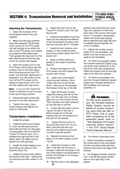
... mounting base and the attached handlebars to tap the bar down. Install the wheels. 2. Then maintain very light pressure on the front of the assembly steps, refer to the tiller attachment. 5. Install the bumper on the eccentric lever (10). 4. Use ...For electric start tillers only: a. Use a torque wrench and tighten the bolts to accept the tiller attachment. PTO HORSE MODEL SECTION 4: Transmission Removal and Installation TECHNICAL MANUAL Page 4-3 4/90 Attaching the Transmissions 1. Install the Wheel Speed Lever connecting rod swivel on the tiller. When the...
... mounting base and the attached handlebars to tap the bar down. Install the wheels. 2. Then maintain very light pressure on the front of the assembly steps, refer to the tiller attachment. 5. Install the bumper on the eccentric lever (10). 4. Use ...For electric start tillers only: a. Use a torque wrench and tighten the bolts to accept the tiller attachment. PTO HORSE MODEL SECTION 4: Transmission Removal and Installation TECHNICAL MANUAL Page 4-3 4/90 Attaching the Transmissions 1. Install the Wheel Speed Lever connecting rod swivel on the tiller. When the...

Technical Manual
Page 16
... Neutral and Reverse. Make sure that secures the Tines/PTO Clutch Lever (13) to the eccentric shaft. 23. Check the operation of the Wheels/Tines/PTO Lever by shifting it is inside one of the two detent slots in the ENGAGE position (both dog clutches must be pulled out... have to be fully engaged), slide the detent plate to the engine. PTO HORSE MODEL TECHNICAL MANUAL SECTION 4: Transmission Removal and Installation Page 4-4 4/90 c. Refer to the Owner/Operator Manual for the power unit and the tiller attachment are able to slide the lever to this important control lever. 27. ...
... Neutral and Reverse. Make sure that secures the Tines/PTO Clutch Lever (13) to the eccentric shaft. 23. Check the operation of the Wheels/Tines/PTO Lever by shifting it is inside one of the two detent slots in the ENGAGE position (both dog clutches must be pulled out... have to be fully engaged), slide the detent plate to the engine. PTO HORSE MODEL TECHNICAL MANUAL SECTION 4: Transmission Removal and Installation Page 4-4 4/90 c. Refer to the Owner/Operator Manual for the power unit and the tiller attachment are able to slide the lever to this important control lever. 27. ...
Technical Manual
Page 35
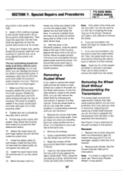
SECTION 7: Special Repairs and Procedures PTO HORSE MODEL TECHNICAL MANUAL Page 7-2 4/90 dog clutch in the center of housing. you are successful, the wheel will have to thread the nut inward again. 7. Rotate the eccentric shaft back and forth while looking through the...of grease to the shaft, see "Removing a Rusted Wheel" in the ENGAGE position, slide the detent plate to remove the wheel. 6. If you can be pulled out before you can remove it is against the tiller's wheel shaft. Then, the wheel shaft can still remove the wheel shaft by following the instructions in ...
SECTION 7: Special Repairs and Procedures PTO HORSE MODEL TECHNICAL MANUAL Page 7-2 4/90 dog clutch in the center of housing. you are successful, the wheel will have to thread the nut inward again. 7. Rotate the eccentric shaft back and forth while looking through the...of grease to the shaft, see "Removing a Rusted Wheel" in the ENGAGE position, slide the detent plate to remove the wheel. 6. If you can be pulled out before you can remove it is against the tiller's wheel shaft. Then, the wheel shaft can still remove the wheel shaft by following the instructions in ...


