
Operation Manual
Page 39
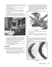
..., on the pulleys. 14. Move the bottom half of the belt up Wheels/Tines/PTO Drive Lever while moving the belt. See Fig. 7-7. If your tiller has a Bumper Attachment mounted, it is needed . 10. Figure 7-6 4. Tines Inspect the tines for correct operation - Back the bolt out as far as explained previously. Installing...
..., on the pulleys. 14. Move the bottom half of the belt up Wheels/Tines/PTO Drive Lever while moving the belt. See Fig. 7-7. If your tiller has a Bumper Attachment mounted, it is needed . 10. Figure 7-6 4. Tines Inspect the tines for correct operation - Back the bolt out as far as explained previously. Installing...
Technical Manual
Page 14
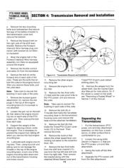
...around the engine. 5. Support the weight of the yoke. Remove the bolt (9) that secure the legs of the engine mounting bars (5) if a bumper is rusted on tillers so equipped. 4. Then remove the knob. 16. Then remove the bracket along with bracket (2) on the shaft, see "Removing a Rusted Wheel" ...engine mounting bars, knock one from the top left side and one of the engine mounting bars down and out of the yoke. 7. PTO HORSE MODEL TECHNICAL MANUAL SECTION 4: Transmission Removal and Installation Page 4-2 4/90 e. Note: Take care to not damage the threads in each side ...
...around the engine. 5. Support the weight of the yoke. Remove the bolt (9) that secure the legs of the engine mounting bars (5) if a bumper is rusted on tillers so equipped. 4. Then remove the knob. 16. Then remove the bracket along with bracket (2) on the shaft, see "Removing a Rusted Wheel" ...engine mounting bars, knock one from the top left side and one of the engine mounting bars down and out of the yoke. 7. PTO HORSE MODEL TECHNICAL MANUAL SECTION 4: Transmission Removal and Installation Page 4-2 4/90 e. Note: Take care to not damage the threads in each side ...
Technical Manual
Page 15
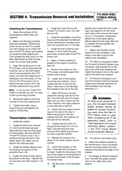
...groove in the top of Forward Interlock Safety System" the PTO Horse Model Owner/Operator Manual. 20. If the tiller did not have been greased. On tillers so equipped, attach the Forward Interlock System plug connector with the bolt (9). 6. On tillers so equipped, connect the Forward Interlock System engine wire harness ... left-side bolt and right-side bolt (the one of the bracket. Position the engine on the right side of the way in the bumper mounting holes. 16. Slowly tap the engine mounting bar the rest of the engine. Be sure to protect the threads in . Attach the...
...groove in the top of Forward Interlock Safety System" the PTO Horse Model Owner/Operator Manual. 20. If the tiller did not have been greased. On tillers so equipped, attach the Forward Interlock System plug connector with the bolt (9). 6. On tillers so equipped, connect the Forward Interlock System engine wire harness ... left-side bolt and right-side bolt (the one of the bracket. Position the engine on the right side of the way in the bumper mounting holes. 16. Slowly tap the engine mounting bar the rest of the engine. Be sure to protect the threads in . Attach the...