Tripp Lite DWMSCP4570VW Support and Manuals
Get Help and Manuals for this Tripp Lite item
View All Support Options Below
Free Tripp Lite DWMSCP4570VW manuals!
Problems with Tripp Lite DWMSCP4570VW?
Ask a Question
Free Tripp Lite DWMSCP4570VW manuals!
Problems with Tripp Lite DWMSCP4570VW?
Ask a Question
Popular Tripp Lite DWMSCP4570VW Manual Pages
933F11 - Page 1
....com/warranty
1111 W. 35th Street, Chicago, IL 60609 USA • tripplite.com/support Copyright © 2021 Tripp Lite. SERIOUS INJURY OR PROPERTY DAMAGE MAY OCCUR!
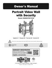
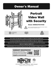
200x200/... automatically entered to win an ISOBAR® surge protector in our monthly drawing! Owner's Manual
Portrait Video Wall with Security
Model: DWMSCP4570VW
Español 17 • Français 33 49 • Deutsch...
933F11 - Page 2

... defects in material and workmanship for a period of the equipment and all the instructions and warnings contained in damage or serious
personal injury. • Safety gear and proper tools must be installed by professionals. • Ensure the supporting surface will repair or replace the product, at least every three months). Overtightening
can cause damage to...
933F11 - Page 3
... W
M-B
M6x14 (x4)
M-F
Washer (x4)
M-C
M8x20 (x4)
M-D
M6x30 (x4)
M-G
Small Spacer (x8)
M-H
Large Spacer (x4)
W-A
ST6.3x55 (x6)
W-B
Concrete Anchor (x6)
3
W-C
D6 Washer (x6)
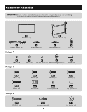
If any parts are missing or faulty, visit tripplite.com/support for service. Component Checklist
IMPORTANT: Ensure you have received all parts according to the component checklist prior to installing.
933F11 - Page 4
1.
Drill pilot holes
A
W-B
Screw the wall mount onto the wall. W-C W-A
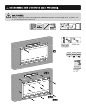
4 Solid Brick and Concrete Wall Mounting
WARNING
Installers must verify that the supporting surface will safely support the combined weight of the equipment and
all attached hardware and components.
29.54"mm ((630.7m")m)
Ø 3/8" (Ø 10 mm)
1
2
Mark the exact location of the mounting holes.
933F11 - Page 7
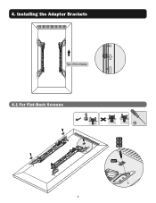
Installing the Adapter Brackets
Top of the display
4.1 For Flat-Back Screens
TV
TV
TV
M-A M-B M-C
M-F
7 4.
933F11 - Page 16
... Bracket Positions with the Plastic Locking Pieces
I
Top View
Side View
1111 W. 35th Street, Chicago, IL 60609 USA • tripplite.com/support 16
21-06-106 933F11_RevA J
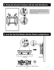
9. 8. Lock the Pop-Out Module with the Anti-Skid Blocks
H
Install both of the anti-skid blocks as close to prevent the
display from moving.
933F12 - Page 1
...8226; tripplite.com/support Copyright © 2021 Tripp Lite.
All rights reserved. 1 SERIOUS INJURY OR PROPERTY DAMAGE MAY OCCUR!
200x200/300x300 200x400/400x400 400x600
70" MAX
154 lb. (70 kg) RATED
Este manual esta disponible en... protector in our monthly drawing! Owner's Manual
Portrait Video Wall with Security
Model: DWMSCP4570VW
CAUTION: DO NOT EXCEED MAXIMUM LISTED WEIGHT CAPACITY.
933F12 - Page 2
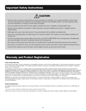
... DURATION TO THE WARRANTY PERIOD SET FORTH ABOVE; Some restrictions apply. Keep these instructions. If the product should take care to determine prior to change without notice. Void where prohibited. Important Safety Instructions
CAUTION
• Read the entire instruction manual before you have questions about any specific application. Do not begin installation until you start assembly...
933F12 - Page 3

Component Checklist
IMPORTANT: Ensure you have received all parts according to the component checklist prior to installing. A
Wall Plate (x1)
C
Adapter Bracket (x2)
Package P
D
VESA Adapter (x2)
B
Pop-Out Module (x1)
E
...x8)
M-H
Large Spacer (x4)
W-A
ST6.3x55 (x6)
W-B
Concrete Anchor (x6)
3
W-C
D6 Washer (x6) If any parts are missing or faulty, visit tripplite.com/support for service.
933F12 - Page 4

Drill pilot holes
A
W-B
Screw the wall mount onto the wall.
W-C W-A
4 1. Solid Brick and Concrete Wall Mounting
WARNING
Installers must verify that the supporting surface will safely support the combined weight of the equipment and
all attached hardware and components.
29.54"mm ((630.7m")m)
Ø 3/8" (Ø 10 mm)
1
2
Mark the exact location of the mounting holes.
933F12 - Page 5
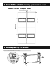
Y = 0.2" (5 mm) Y = 0.2" (5 mm)
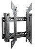
2. Installing the Pop-Out Module
Remove caps before installing the pop-out module. Video Wall Installation (mounting space as shown below)
3. B
5
933F12 - Page 6
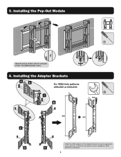
3. Installing the Pop-Out Module
Hang the pop-up module onto the wall plate. Secure it by tightening both screws.
4. Installing the Adapter Brackets
G
E
For VESA hole patterns 400x400 or 600x400
F D
C D
Attach the VESA adapters to the adapter brackets using the appropriate
screws and nuts so that the hole pattern can be expanded to VESA
E
400x400 or 600x400.
6
933F12 - Page 7
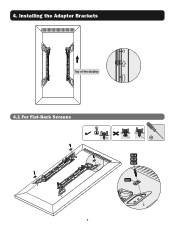
Installing the Adapter Brackets
4.1 For Flat-Back Screens
TV
TV
TV
M-A M-B M-C
M-F
7 4.
933F12 - Page 15
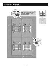
7.
Note: Install and adjust displays in the numerical order shown. I
15
Level the Displays
E Note: Use the plastic locking piece E
to measure and keep a 1.2 mm gap between displays.
933F12 - Page 16

Fixing the Bracket Positions with the Plastic Locking Pieces
I
Top View
Side View
1111 W. 35th Street, Chicago, IL 60609 USA • tripplite.com/support 16
21-06-105 933F12_RevA
8. J
9. Tighten screws on
the anti-skid blocks using a hex key to the
adapter brackets as close to prevent the
display ...
Tripp Lite DWMSCP4570VW Reviews
We have not received any reviews for Tripp Lite yet.