
Toshiba Online Users Guide for Tecra M5
Page 26
Contents Introduction 36 This guide 37 Safety icons 38 Other icons used 39 Other documentation 39 Service options 40 Chapter 1: Getting Started 41 Selecting a place to work 41 Creating a computer-friendly environment........41 Keeping yourself comfortable 42 Precautions 42 Important information on your computer's cooling fan 45 Setting up your computer 45 Setting up your software 46 Registering your computer with Toshiba 47 Adding external devices 47 Connecting to a power source 48 Using the main battery 51 26
Contents Introduction 36 This guide 37 Safety icons 38 Other icons used 39 Other documentation 39 Service options 40 Chapter 1: Getting Started 41 Selecting a place to work 41 Creating a computer-friendly environment........41 Keeping yourself comfortable 42 Precautions 42 Important information on your computer's cooling fan 45 Setting up your computer 45 Setting up your software 46 Registering your computer with Toshiba 47 Adding external devices 47 Connecting to a power source 48 Using the main battery 51 26
Toshiba Online Users Guide for Tecra M5
Page 45
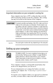
.... To register your computer online or to a power source" on page 48. Getting Started Setting up your computer 45 Important information on your computer's cooling fan Your computer may be located on the bottom of the CPU, make sure the air intake on the cooling... fan is blocked, it . If the fan is not blocked. See "Connecting to sign up for an Internet account, you must either connect the built-in modem to your computer. Loose items ...
.... To register your computer online or to a power source" on page 48. Getting Started Setting up your computer 45 Important information on your computer's cooling fan Your computer may be located on the bottom of the CPU, make sure the air intake on the cooling... fan is blocked, it . If the fan is not blocked. See "Connecting to sign up for an Internet account, you must either connect the built-in modem to your computer. Loose items ...

Maintenance Manual
Page 8
... 4-39 4.14 Sound board ...4-40 4.15 RTC battery...4-42 4.16 Video board...4-44 4.17 GPU heat sink ...4-46 4.18 CPU heat sink/CPU 4-48 4.19 Fan...4-52 4.20 System board/HDD cable/DC-IN jack 4-54 4.21 LAN/Modem jack ...4-57 4.22 PC card slot ...4-58 4.23 Battery lock/Battery latch.../FL inverter 4-61 4.25 Touch pad...4-66 4.26 Finger print sensor board 4-68 4.27 Bluetooth module...4-70 4.28 Hinge...4-72 4.29 Speaker...4-78 viii [CONFIDENTIAL] TECRA M5 Maintenance Manual (960-542)
... 4-39 4.14 Sound board ...4-40 4.15 RTC battery...4-42 4.16 Video board...4-44 4.17 GPU heat sink ...4-46 4.18 CPU heat sink/CPU 4-48 4.19 Fan...4-52 4.20 System board/HDD cable/DC-IN jack 4-54 4.21 LAN/Modem jack ...4-57 4.22 PC card slot ...4-58 4.23 Battery lock/Battery latch.../FL inverter 4-61 4.25 Touch pad...4-66 4.26 Finger print sensor board 4-68 4.27 Bluetooth module...4-70 4.28 Hinge...4-72 4.29 Speaker...4-78 viii [CONFIDENTIAL] TECRA M5 Maintenance Manual (960-542)

Maintenance Manual
Page 76
...parameters for 2HD (1.44MB) Reading of first sector, If it is the data of "CHGBIOSA.EXE" and "CHGFIRMA.EXE" 2-22 [CONFIDENTIAL] TECRA M5 Maintenance Manual (960-542) 2 Troubleshooting Procedures 2.4 System Board Troubleshooting Table 2-5 Printer port LED boot mode status (2/9) LED Status B9h Test item ...Saving of key scan code Setting of TASK_1ms_TSC FAN control Sound initialization (for BEEP sound) When BIOS, EC/KBC rewriting is requested When BIOS renewal is prohibited When BIOS ROM is...
...parameters for 2HD (1.44MB) Reading of first sector, If it is the data of "CHGBIOSA.EXE" and "CHGFIRMA.EXE" 2-22 [CONFIDENTIAL] TECRA M5 Maintenance Manual (960-542) 2 Troubleshooting Procedures 2.4 System Board Troubleshooting Table 2-5 Printer port LED boot mode status (2/9) LED Status B9h Test item ...Saving of key scan code Setting of TASK_1ms_TSC FAN control Sound initialization (for BEEP sound) When BIOS, EC/KBC rewriting is requested When BIOS renewal is prohibited When BIOS ROM is...

Maintenance Manual
Page 136
Fan ON/OFF 05 - Selecting YES of TEST LOOP increases the pass counter by your computer may be slightly different from the subtest menu and press ... cursor to DIAGNOSTIC TEST MENU : XXXXX : XX : XXX NOTE: The menu displayed by one shown above. Exit to the desired option and press Enter. 3-6 [CONFIDENTIAL] TECRA M5 Maintenance Manual (960-542) Select the desired subtest number from the one , each time the test cycle ends and restarts the test cycle. ROM checksum...
Fan ON/OFF 05 - Selecting YES of TEST LOOP increases the pass counter by your computer may be slightly different from the subtest menu and press ... cursor to DIAGNOSTIC TEST MENU : XXXXX : XX : XXX NOTE: The menu displayed by one shown above. Exit to the desired option and press Enter. 3-6 [CONFIDENTIAL] TECRA M5 Maintenance Manual (960-542) Select the desired subtest number from the one , each time the test cycle ends and restarts the test cycle. ROM checksum...

Maintenance Manual
Page 141
... 03 04 05 Subtest Name ROM checksum Fan ON/OFF Geyserville Quick charge DMI read Conventional memory Protected Mode Protected Mode (cache off) Cache memory (on/off) Stress Pressed key code display VRAM read /write Random address/data Write specified address Read specified address TECRA M5 Maintenance Manual (960-542) [CONFIDENTIAL] 3-11 3.5 Subtest...
... 03 04 05 Subtest Name ROM checksum Fan ON/OFF Geyserville Quick charge DMI read Conventional memory Protected Mode Protected Mode (cache off) Cache memory (on/off) Stress Pressed key code display VRAM read /write Random address/data Write specified address Read specified address TECRA M5 Maintenance Manual (960-542) [CONFIDENTIAL] 3-11 3.5 Subtest...

Maintenance Manual
Page 143
...The following message will appear. *** Test Fan Revolution Low speed Start Make sure the fan rotates at high speed and the message of fan revolution for it changes. The following message will stop and return to execute and press Enter. TECRA M5 Maintenance Manual (960-542) [CONFIDENTIAL] ...3-13 After a while, the fan rotating will appear. *** Test Fan Revolution High speed Start Make sure the fan rotates at low speed and the message of fan revolution for the quick charge. Then ...
...The following message will appear. *** Test Fan Revolution Low speed Start Make sure the fan rotates at high speed and the message of fan revolution for it changes. The following message will stop and return to execute and press Enter. TECRA M5 Maintenance Manual (960-542) [CONFIDENTIAL] ...3-13 After a while, the fan rotating will appear. *** Test Fan Revolution High speed Start Make sure the fan rotates at low speed and the message of fan revolution for the quick charge. Then ...

Maintenance Manual
Page 219
... Battery Save Mode When "User Setting" is selected, the sub-window, BATTERY SAVE OPTION is lowered automatically. Maximum performance Turns on the fan first, and if necessary, lowers CPU processing speed. (Default) Battery optimized Lowers the CPU processing speed first, and if necessary, turns ... Use this option to enable or disable the CPU sleep function. CPU Sleep Mode Use this option to a normal range, the fan turns off. TECRA M5 Maintenance Manual (960-542) [CONFIDENTIAL] 3-89 Super-Bright Full brightness for saving power. When the CPU temperature falls to set ...
... Battery Save Mode When "User Setting" is selected, the sub-window, BATTERY SAVE OPTION is lowered automatically. Maximum performance Turns on the fan first, and if necessary, lowers CPU processing speed. (Default) Battery optimized Lowers the CPU processing speed first, and if necessary, turns ... Use this option to enable or disable the CPU sleep function. CPU Sleep Mode Use this option to a normal range, the fan turns off. TECRA M5 Maintenance Manual (960-542) [CONFIDENTIAL] 3-89 Super-Bright Full brightness for saving power. When the CPU temperature falls to set ...

Maintenance Manual
Page 233
... 4-39 4.14 Sound board ...4-40 4.15 RTC battery ...4-42 4.16 Video board...4-44 4.17 GPU heat sink ...4-46 4.18 CPU heat sink/CPU 4-48 4.19 Fan...4-52 4.20 System board/HDD cable/DC-IN jack 4-54 4.21 LAN/Modem jack ...4-57 4.22 PC card slot ...4-58 4.23 Battery lock/Battery latch... pad...4-66 4.26 Finger print sensor board 4-68 4.27 Bluetooth module...4-70 4.28 Hinge...4-72 4.29 Speaker...4-78 4.30 Wireless LAN antenna/Bluetooth antenna 4-80 TECRA M5 Maintenance Manual (960-542) [CONFIDENTIAL] 4-iii
... 4-39 4.14 Sound board ...4-40 4.15 RTC battery ...4-42 4.16 Video board...4-44 4.17 GPU heat sink ...4-46 4.18 CPU heat sink/CPU 4-48 4.19 Fan...4-52 4.20 System board/HDD cable/DC-IN jack 4-54 4.21 LAN/Modem jack ...4-57 4.22 PC card slot ...4-58 4.23 Battery lock/Battery latch... pad...4-66 4.26 Finger print sensor board 4-68 4.27 Bluetooth module...4-70 4.28 Hinge...4-72 4.29 Speaker...4-78 4.30 Wireless LAN antenna/Bluetooth antenna 4-80 TECRA M5 Maintenance Manual (960-542) [CONFIDENTIAL] 4-iii

Maintenance Manual
Page 235
... CPU holder 4-48 Figure 4-32 Unlocking the CPU 4-49 Figure 4-33 Installing the CPU 4-50 Figure 4-34 Applying new grease 4-51 Figure 4-35 Removing the fan 4-52 Figure 4-36 Removing the system board/HDD cable/DC-IN jack (1 4-54 Figure 4-37 Removing the system board/HDD cable/DC-IN jack (2 4-55... LAN/Bluetooth antenna 4-80 Figure 4-56 Removing the LCD cover latch 4-82 Figure 4-57 to 4-60 Replacing Samsung fluorescent lamp (XGA)) (1) to (4) .......4-84 to 4-86 TECRA M5 Maintenance Manual (960-542) [CONFIDENTIAL] 4-v
... CPU holder 4-48 Figure 4-32 Unlocking the CPU 4-49 Figure 4-33 Installing the CPU 4-50 Figure 4-34 Applying new grease 4-51 Figure 4-35 Removing the fan 4-52 Figure 4-36 Removing the system board/HDD cable/DC-IN jack (1 4-54 Figure 4-37 Removing the system board/HDD cable/DC-IN jack (2 4-55... LAN/Bluetooth antenna 4-80 Figure 4-56 Removing the LCD cover latch 4-82 Figure 4-57 to 4-60 Replacing Samsung fluorescent lamp (XGA)) (1) to (4) .......4-84 to 4-86 TECRA M5 Maintenance Manual (960-542) [CONFIDENTIAL] 4-v

Maintenance Manual
Page 288
Remove the following screws securing the fan. • M2.5×4B FLAT HEAD screw ×2 2. Peel off the glass tape and disconnect the fan cable from the slot. 4 Replacement Procedures 4.19 Fan 4.19 Fan Removing the Fan To remove the fan, follow the steps below and refer to Figure 4-35. 1. Remove the fan from the connector CN8771 on the system board. 3. Glass tape M2.5×4B FLAT HEAD Fan cable M2.5×4B FLAT HEAD Fan CN8771 Figure4-35 Removing the fan 4-52 [CONFIDENTIAL] TECRA M5 Maintenance Manual (960-542)
Remove the following screws securing the fan. • M2.5×4B FLAT HEAD screw ×2 2. Peel off the glass tape and disconnect the fan cable from the slot. 4 Replacement Procedures 4.19 Fan 4.19 Fan Removing the Fan To remove the fan, follow the steps below and refer to Figure 4-35. 1. Remove the fan from the connector CN8771 on the system board. 3. Glass tape M2.5×4B FLAT HEAD Fan cable M2.5×4B FLAT HEAD Fan CN8771 Figure4-35 Removing the fan 4-52 [CONFIDENTIAL] TECRA M5 Maintenance Manual (960-542)

Maintenance Manual
Page 289
Secure the fan cable with the following screws. • M2.5×4B FLAT HEAD screw ×2 TECRA M5 Maintenance Manual (960-542) [CONFIDENTIAL] 4-53 Install the fan to Figure 4-35. 1. Secure the fan with the glass tape. 4. 4.19 Fan 4 Replacement Procedures Installing the Fan To install the fan, follow the steps below and refer to the slot. 2. Connect the fan cable to the connector CN8771 on the system board. 3.
Secure the fan cable with the following screws. • M2.5×4B FLAT HEAD screw ×2 TECRA M5 Maintenance Manual (960-542) [CONFIDENTIAL] 4-53 Install the fan to Figure 4-35. 1. Secure the fan with the glass tape. 4. 4.19 Fan 4 Replacement Procedures Installing the Fan To install the fan, follow the steps below and refer to the slot. 2. Connect the fan cable to the connector CN8771 on the system board. 3.

Maintenance Manual
Page 332
... C.22 CN8800 DC-IN connector (4-pin C-22 C.23 CN8810 1st Battery connector (10-pin C-22 C.24 CN9390 RTC Battery connector (3-pin C-22 C.25 CN8771 FAN interface connector (4-pin C-22 C.26 CN9500 GN board interface connector (40-pin C-23 C.27 CN9501 GN board interface connector (10-pin C-23 C.28 CN9700 GF...E.1 United Kingdom (UK) Keyboard E-1 E.2 United States (US) Keyboard E-1 Appendix F Wiring Diagrams F-1 F.1 Serial Port Wraparound Connector F-1 F.2 LAN Loopback Connector F-1 Appendix G BIOS rewrite Procedures G-1 App-iv [CONFIDENTIAL] TECRA M5 Maintenance Manual (960-542)
... C.22 CN8800 DC-IN connector (4-pin C-22 C.23 CN8810 1st Battery connector (10-pin C-22 C.24 CN9390 RTC Battery connector (3-pin C-22 C.25 CN8771 FAN interface connector (4-pin C-22 C.26 CN9500 GN board interface connector (40-pin C-23 C.27 CN9501 GN board interface connector (10-pin C-23 C.28 CN9700 GF...E.1 United Kingdom (UK) Keyboard E-1 E.2 United States (US) Keyboard E-1 Appendix F Wiring Diagrams F-1 F.1 Serial Port Wraparound Connector F-1 F.2 LAN Loopback Connector F-1 Appendix G BIOS rewrite Procedures G-1 App-iv [CONFIDENTIAL] TECRA M5 Maintenance Manual (960-542)

Maintenance Manual
Page 344
... CN5300 IS1050 IC2000 IC1600 IC3200 IC5000 Name Network interface connector Main Battery connector DC-IN connector Modem relay connector RGB connector PCI Express card connector Fan connector LCD interface connector IEEE1394 connector USB port 0 connector PC card interface connector Select bay connector GN board I/F connector USB harness connector GF board I/F connector...
... CN5300 IS1050 IC2000 IC1600 IC3200 IC5000 Name Network interface connector Main Battery connector DC-IN connector Modem relay connector RGB connector PCI Express card connector Fan connector LCD interface connector IEEE1394 connector USB port 0 connector PC card interface connector Select bay connector GN board I/F connector USB harness connector GF board I/F connector...


