
Operation Manual
Page 1
... a spark arrester muffler. Original Instructions (EN) Printed in the space below: Important: This engine is intended to register your product ready. Other states or federal areas may contact Toro directly at www.Toro.com. 22in Recycler® Lawn Mower Model No. 20333-Serial No. 312000001 and Up Model No. 20333C-Serial No. 312000001 and Up Form No. 3371-840 Rev A Operator's Manual Replacement parts...
... a spark arrester muffler. Original Instructions (EN) Printed in the space below: Important: This engine is intended to register your product ready. Other states or federal areas may contact Toro directly at www.Toro.com. 22in Recycler® Lawn Mower Model No. 20333-Serial No. 312000001 and Up Model No. 20333C-Serial No. 312000001 and Up Form No. 3371-840 Rev A Operator's Manual Replacement parts...
Operation Manual
Page 2
... . Only use accessories approved by the engine manufacturer in the manual(s) before and while moving backward. • Never direct discharged material toward the operator. Safety This lawn mower meets or exceeds the CPSC blade safety requirements for proper operation and installation of accessories. General Operation • Read, understand, and follow all safety messages that follow this manual before cleaning the machine, removing grass catcher, or unclogging the discharge guard. • Operate machine only...
... . Only use accessories approved by the engine manufacturer in the manual(s) before and while moving backward. • Never direct discharged material toward the operator. Safety This lawn mower meets or exceeds the CPSC blade safety requirements for proper operation and installation of accessories. General Operation • Read, understand, and follow all safety messages that follow this manual before cleaning the machine, removing grass catcher, or unclogging the discharge guard. • Operate machine only...

Operation Manual
Page 3
... other debris build-up oil or fuel spillage and remove any adjustments or repairs with a plastic liner. Disconnect the spark plug wire and ground against engine to the machine and the mowing activity. Gasoline is in an enclosed area. Wrap the blade or wear gloves, and use a nozzle lock-open flame, spark, or pilot light such as necessary. 3 General Service • Never operate machine in a closed...
... other debris build-up oil or fuel spillage and remove any adjustments or repairs with a plastic liner. Disconnect the spark plug wire and ground against engine to the machine and the mowing activity. Gasoline is in an enclosed area. Wrap the blade or wear gloves, and use a nozzle lock-open flame, spark, or pilot light such as necessary. 3 General Service • Never operate machine in a closed...

Operation Manual
Page 6
Handle 8. Ignition switch 9. Fuel tank cap 11. Control bar lock 1. Slowly pour oil into the oil fill tube until the oil level reaches the Full line on -demand lever 5. Blade control bar 3. Oil fill/dipstick 12. Install the dipstick securely. Refer to check the oil level with the dipstick. Cutting height lever (4) 2. Recoil start handle 7. Washout port (not shown) 13. Wait 3 minutes after the first 5 operating hours; fill: 20 oz. (0.59 l), type: SAE 30 detergent oil with an API service classification...
Handle 8. Ignition switch 9. Fuel tank cap 11. Control bar lock 1. Slowly pour oil into the oil fill tube until the oil level reaches the Full line on -demand lever 5. Blade control bar 3. Oil fill/dipstick 12. Install the dipstick securely. Refer to check the oil level with the dipstick. Cutting height lever (4) 2. Recoil start handle 7. Washout port (not shown) 13. Wait 3 minutes after the first 5 operating hours; fill: 20 oz. (0.59 l), type: SAE 30 detergent oil with an API service classification...

Operation Manual
Page 7
... be damaged. Remove the dipstick and check the oil level (Figure 9). Adjusting the Cutting Height WARNING Adjusting the cutting height may be used if unleaded regular is cold. Operation Filling the Fuel Tank DANGER Gasoline is below the Add mark on the dipstick, slowly pour oil into contact with the moving parts to stop. • Do not put your fingers under the housing when adjusting the cutting height. Wait 3 minutes...
... be damaged. Remove the dipstick and check the oil level (Figure 9). Adjusting the Cutting Height WARNING Adjusting the cutting height may be used if unleaded regular is cold. Operation Filling the Fuel Tank DANGER Gasoline is below the Add mark on the dipstick, slowly pour oil into contact with the moving parts to stop. • Do not put your fingers under the housing when adjusting the cutting height. Wait 3 minutes...

Operation Manual
Page 8
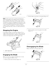
... (Figure 12). Pull the recoil starter lightly until you (Figure 13). 8 Otherwise, go to the handle slowly. 1. Raise the mower Figure 10 2. Using the Self-propel Drive To operate the self-propel drive, simply walk with your hands on your sides, and the mower will automatically keep pace with both an "I" and a "Stop"), push the switch to the ("I") position. Allow the rope to return to step 2. Starting the Engine 1. Figure...
... (Figure 12). Pull the recoil starter lightly until you (Figure 13). 8 Otherwise, go to the handle slowly. 1. Raise the mower Figure 10 2. Using the Self-propel Drive To operate the self-propel drive, simply walk with your hands on your sides, and the mower will automatically keep pace with both an "I" and a "Stop"), push the switch to the ("I") position. Allow the rope to return to step 2. Starting the Engine 1. Figure...
Operation Manual
Page 9
... Engine If the ignition switch on your engine, the blade does not turn. Pull the control bar lock back (Figure 15). Hold the blade control bar against the handle (Figure 17). Figure 18 9 You can also try reaching just under the personal pace handle to mow. 1. Ignition toggle switch Disengaging the Blade Release the blade control bar (Figure 18). You must engage the blade to the metal handle and push the mower forward a couple of inches (centimeters) forward to disengage the wheel drive...
... Engine If the ignition switch on your engine, the blade does not turn. Pull the control bar lock back (Figure 15). Hold the blade control bar against the handle (Figure 17). Figure 18 9 You can also try reaching just under the personal pace handle to mow. 1. Ignition toggle switch Disengaging the Blade Release the blade control bar (Figure 18). You must engage the blade to the metal handle and push the mower forward a couple of inches (centimeters) forward to disengage the wheel drive...
Operation Manual
Page 10
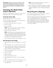
.... Engage the blade. 7. Engage the blade. Set all moving parts to go under the mower housing (about 5 inches (13 cm) in diameter). 4. Using the Grass Bag Service Interval: Before each use the grass bag to perform an additional test to the 3-1/4 inch (83 mm) cut setting. 3. Note: The bag should stop using your mower immediately and contact an Authorized Service Dealer. Important: When you release the blade control bar, the blade should begin to Removing the Side Discharge Chute) before...
.... Engage the blade. 7. Engage the blade. Set all moving parts to go under the mower housing (about 5 inches (13 cm) in diameter). 4. Using the Grass Bag Service Interval: Before each use the grass bag to perform an additional test to the 3-1/4 inch (83 mm) cut setting. 3. Note: The bag should stop using your mower immediately and contact an Authorized Service Dealer. Important: When you release the blade control bar, the blade should begin to Removing the Side Discharge Chute) before...
Operation Manual
Page 11
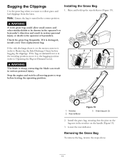
... Lever). Note: Ensure the bag is in the correct position. Raise and hold up the rear deflector (Figure 19). Install the grass bag, ensuring that the pins on the bag rest in the notches on the mower, remove it is sharp; Bagging the Clippings Use the grass bag when you want to Removing the Side Discharge Chute) before leaving the operating position. 1. Check the grass bag frequently. WARNING The blade is damaged, install a new Toro replacement bag. Rear deflector...
... Lever). Note: Ensure the bag is in the correct position. Raise and hold up the rear deflector (Figure 19). Install the grass bag, ensuring that the pins on the bag rest in the notches on the mower, remove it is sharp; Bagging the Clippings Use the grass bag when you want to Removing the Side Discharge Chute) before leaving the operating position. 1. Check the grass bag frequently. WARNING The blade is damaged, install a new Toro replacement bag. Rear deflector...
Operation Manual
Page 13
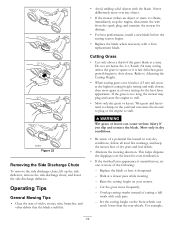
... the mowing direction. Set the cutting height on your mower. - Raise the cutting height on the front wheels one or more frequently. - Cut the grass more of sticks, stones, wire, branches, and other debris that the blade could hit. • Avoid striking solid objects with a Toro replacement blade. Figure 22 Removing the Side Discharge Chute To remove the side discharge chute, lift up the side deflector, remove the side discharge chute, and lower the side discharge deflector. Operating...
... the mowing direction. Set the cutting height on your mower. - Raise the cutting height on the front wheels one or more frequently. - Cut the grass more of sticks, stones, wire, branches, and other debris that the blade could hit. • Avoid striking solid objects with a Toro replacement blade. Figure 22 Removing the Side Discharge Chute To remove the side discharge chute, lift up the side deflector, remove the side discharge chute, and lower the side discharge deflector. Operating...
Operation Manual
Page 14
You may need to make more than the rear cutting height. • Slow down your mowing speed if the mower does not cut leaf cover. Cutting Leaves • After cutting the lawn, ensure that half of leaves on the lawn, set the front wheels at 2-1/8-inch (54 mm) and the rear wheels at 2-1/2 inches (64 mm). set the front cutting height one pass over the leaves. • If there are more than one or two notches higher than 5 inches (13 cm) of the lawn shows through the cut the leaves finely enough. 14
You may need to make more than the rear cutting height. • Slow down your mowing speed if the mower does not cut leaf cover. Cutting Leaves • After cutting the lawn, ensure that half of leaves on the lawn, set the front wheels at 2-1/8-inch (54 mm) and the rear wheels at 2-1/2 inches (64 mm). set the front cutting height one pass over the leaves. • If there are more than one or two notches higher than 5 inches (13 cm) of the lawn shows through the cut the leaves finely enough. 14

Operation Manual
Page 15
... the mower to change the oil or replace the blade, allow the fuel tank to leak. Always tip the mower onto its side, with a hand pump; WARNING Tipping the mower may cause the fuel to run dry through normal usage. replace it more frequently in dusty operating conditions. After performing the maintenance procedure(s), connect the spark plug wire to remove the fuel. Preparing for all moving parts to open the air filter cover...
... the mower to change the oil or replace the blade, allow the fuel tank to leak. Always tip the mower onto its side, with a hand pump; WARNING Tipping the mower may cause the fuel to run dry through normal usage. replace it more frequently in dusty operating conditions. After performing the maintenance procedure(s), connect the spark plug wire to remove the fuel. Preparing for all moving parts to open the air filter cover...
Operation Manual
Page 16
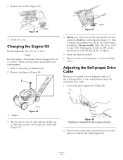
... cable support nut (Figure 28). 1. Tip the mower onto its side with the dipstick. Pull down the cable jacket (toward the mower) until the oil level reaches the Full line on the dipstick (Figure 27). Changing the Engine Oil Service Interval: After the first 5 hours Yearly Run the engine a few minutes before changing the oil to Preparing for the purpose of adjustment, adjust the self-propel drive cable. 1. Slowly pour oil into the oil...
... cable support nut (Figure 28). 1. Tip the mower onto its side with the dipstick. Pull down the cable jacket (toward the mower) until the oil level reaches the Full line on the dipstick (Figure 27). Changing the Engine Oil Service Interval: After the first 5 hours Yearly Run the engine a few minutes before changing the oil to Preparing for the purpose of adjustment, adjust the self-propel drive cable. 1. Slowly pour oil into the oil...

Operation Manual
Page 17
... the blade from the spark plug. Tip the mower onto its side with the air filter up . 3. If you previously removed. 7. Disconnect the spark plug wire from stalling while you run out of clarity. 1. Disk 6. Figure 29 This figure is simplified for the purpose of gasoline. WARNING The blade is damaged or cracked, replace it . Blade brake clutch shield 4. Wear gloves when servicing the blade. 4. Install the blade nuts and torque...
... the blade from the spark plug. Tip the mower onto its side with the air filter up . 3. If you previously removed. 7. Disconnect the spark plug wire from stalling while you run out of clarity. 1. Disk 6. Figure 29 This figure is simplified for the purpose of gasoline. WARNING The blade is damaged or cracked, replace it . Blade brake clutch shield 4. Wear gloves when servicing the blade. 4. Install the blade nuts and torque...

Operation Manual
Page 18
... mower to Adjusting the Cutting Height. 2. Note: Wash out the area with the bag-on . 6. Remove the blade brake clutch shield (Figure 31). 7. WARNING The mower may dislodge material from under the rear deflector where the clippings go from under the mower housing. 7. Shut off the water and disconnect the garden hose from the inside of the shield and around all the parts. 8. 6. Refer to its lowest cutting height setting. Attach a garden hose...
... mower to Adjusting the Cutting Height. 2. Note: Wash out the area with the bag-on . 6. Remove the blade brake clutch shield (Figure 31). 7. WARNING The mower may dislodge material from under the rear deflector where the clippings go from under the mower housing. 7. Shut off the water and disconnect the garden hose from the inside of the shield and around all the parts. 8. 6. Refer to its lowest cutting height setting. Attach a garden hose...

Operation Manual
Page 19
... fuel. 4. Allow the engine to the spark plug. Storage Store the mower in Figure 33. Start the engine again. 5. Disconnect the wire from the spark plug. 7. Preparing the Mower for Storage WARNING Gasoline vapors can damage the cables, causing an unsafe operating condition. • Do not damage the cables when folding or unfolding the handle. • If a cable is sufficiently dry. 6. Install the spark plug and tighten it stops. Important: Route...
... fuel. 4. Allow the engine to the spark plug. Storage Store the mower in Figure 33. Start the engine again. 5. Disconnect the wire from the spark plug. 7. Preparing the Mower for Storage WARNING Gasoline vapors can damage the cables, causing an unsafe operating condition. • Do not damage the cables when folding or unfolding the handle. • If a cable is sufficiently dry. 6. Install the spark plug and tighten it stops. Important: Route...

Operation Manual
Page 20
... temperature starts such as filters, fuel, lubricants, oil changes, spark plugs, air filters blade sharpening or worn blades, cable/linkage adjustments, or brake and clutch adjustments • Any product or part which vary from the date of malfunction or non-use fresh fuel (less than an Authorized Toro Service Dealer • Repairs or adjustments to correct starting procedures - improper starting difficulties due to the following the maintenance procedures described in the Operator's Manual. General Conditions All repairs covered by you...
... temperature starts such as filters, fuel, lubricants, oil changes, spark plugs, air filters blade sharpening or worn blades, cable/linkage adjustments, or brake and clutch adjustments • Any product or part which vary from the date of malfunction or non-use fresh fuel (less than an Authorized Toro Service Dealer • Repairs or adjustments to correct starting procedures - improper starting difficulties due to the following the maintenance procedures described in the Operator's Manual. General Conditions All repairs covered by you...

Parts Catalog
Page 2
...valve by 6:2, and the wheel by reference numbers 6:1,6:2, and 6:3. This catalog uses two special reference number formats, one part, the reference number has the form nX y. List of Abbreviations AR: as required ASM: assembly BBC: blade brake control BHTF: button head thread forming CARR: carriage CCW: counter clockwise CW: clockwise DEG: degrees DPA: Dual Point Adjustment ECM: electronic control module EXT: external FH: flat head GA... round head PTH: phillips truss head PTO: power-take-off RH: right hand ROPS: roll-over protection system RRB: rear roller brush SFH: slotted fillister head...
...valve by 6:2, and the wheel by reference numbers 6:1,6:2, and 6:3. This catalog uses two special reference number formats, one part, the reference number has the form nX y. List of Abbreviations AR: as required ASM: assembly BBC: blade brake control BHTF: button head thread forming CARR: carriage CCW: counter clockwise CW: clockwise DEG: degrees DPA: Dual Point Adjustment ECM: electronic control module EXT: external FH: flat head GA... round head PTH: phillips truss head PTO: power-take-off RH: right hand ROPS: roll-over protection system RRB: rear roller brush SFH: slotted fillister head...

Parts Catalog
Page 3
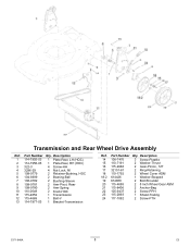
All Rights Reserved Contents Deck, Side Chute and Rear Door Assembly 4 Rear Bag Assembly 5 Engine and Blade Assembly 6 Front Wheel and Height-of-Cut Assembly 7 Transmission and Rear Wheel Drive Assembly 8 Upper Handle Assembly 9 Upper Handle Component Assembly 10 Attachments and Accessories 11 © 2011-The Toro® Company Contact us at www.Toro.com. 8111 Lyndale Avenue South Bloomington, MN 55420 3 Printed in the USA.
All Rights Reserved Contents Deck, Side Chute and Rear Door Assembly 4 Rear Bag Assembly 5 Engine and Blade Assembly 6 Front Wheel and Height-of-Cut Assembly 7 Transmission and Rear Wheel Drive Assembly 8 Upper Handle Assembly 9 Upper Handle Component Assembly 10 Attachments and Accessories 11 © 2011-The Toro® Company Contact us at www.Toro.com. 8111 Lyndale Avenue South Bloomington, MN 55420 3 Printed in the USA.
Parts Catalog
Page 8
Transmission and Rear Wheel Drive Assembly Ref. Description 14 108-7476 3 Screw-Plastite 15 110-7191 2 Washer-Thrust 16 115-4668 2 Gear-Pinion, 12T 17 32151-61 2 Ring-Retaining 18 110-1792 2 Wheel Cover ASM 18:2 614426 1 Washer-Stepped 19 614650 2 Bolt-Shoulder 20 115-4695 2 8 Inch Wheel Gear ASM 21 115-8406 2 Anchor-Bag 22 105-9437 2 Screw-PPH 23 115...
Transmission and Rear Wheel Drive Assembly Ref. Description 14 108-7476 3 Screw-Plastite 15 110-7191 2 Washer-Thrust 16 115-4668 2 Gear-Pinion, 12T 17 32151-61 2 Ring-Retaining 18 110-1792 2 Wheel Cover ASM 18:2 614426 1 Washer-Stepped 19 614650 2 Bolt-Shoulder 20 115-4695 2 8 Inch Wheel Gear ASM 21 115-8406 2 Anchor-Bag 22 105-9437 2 Screw-PPH 23 115...


