

Parts Catalog
Page 6
... 32151-61 2 Ring-Retaining 19 108-7476 3 Screw-Plastite 20 115-4665 2 Gear-Pinion, 13T 21 117-1018 1 V-Belt 3365-712A 6 05 Part Number Qty. Description 1 115-1305 1 Cover-Belt 2 46-8091 2 Screw-HWH 3 115-1956-03 2 Plate-HOC, Front 4 104-8698 2 Retainer-Bearing, HOC 5 ...105-1807 2 Arm-Pivot, Front 6 105-1809 2 Arm-Spring 7 110-1792 7:2 614426 2 Wheel Cover ASM 1 Washer-Stepped 8 614650 2 Bolt-Shoulder 9 115-2878 2 8 Inch Wheel ASM 10 104-8699 2 ...
... 32151-61 2 Ring-Retaining 19 108-7476 3 Screw-Plastite 20 115-4665 2 Gear-Pinion, 13T 21 117-1018 1 V-Belt 3365-712A 6 05 Part Number Qty. Description 1 115-1305 1 Cover-Belt 2 46-8091 2 Screw-HWH 3 115-1956-03 2 Plate-HOC, Front 4 104-8698 2 Retainer-Bearing, HOC 5 ...105-1807 2 Arm-Pivot, Front 6 105-1809 2 Arm-Spring 7 110-1792 7:2 614426 2 Wheel Cover ASM 1 Washer-Stepped 8 614650 2 Bolt-Shoulder 9 115-2878 2 8 Inch Wheel ASM 10 104-8699 2 ...

Parts Catalog
Page 7
Engine and Blade Assembly Ref. Description 1 1 Engine-Briggs, 126T02-0299-B1 ● ■ 2 105-3031-03 1 Guide-Belt 3 106-3999 1 Spacer-Driver 4 106-3987 1 Blade Driver ASM 5 108-9764-03 1 Blade-22 Inch 6 108-3766-03 1 Support-Blade 7 105-8579 1 Bolt-Blade 8 95-1726 3 Screw-Taptite 9 104-7577-03 1 Shield-Muffler 10 32144-1 3 Screw-Taptite 11 2210-316 1 Stop-Rope 12 117-1017 1 Decal ● Not serviced separately 06 ■ Obtain parts from www.briggsandstratton.com 7 3365-712A Part Number Qty.
Engine and Blade Assembly Ref. Description 1 1 Engine-Briggs, 126T02-0299-B1 ● ■ 2 105-3031-03 1 Guide-Belt 3 106-3999 1 Spacer-Driver 4 106-3987 1 Blade Driver ASM 5 108-9764-03 1 Blade-22 Inch 6 108-3766-03 1 Support-Blade 7 105-8579 1 Bolt-Blade 8 95-1726 3 Screw-Taptite 9 104-7577-03 1 Shield-Muffler 10 32144-1 3 Screw-Taptite 11 2210-316 1 Stop-Rope 12 117-1017 1 Decal ● Not serviced separately 06 ■ Obtain parts from www.briggsandstratton.com 7 3365-712A Part Number Qty.
Service Manual
Page 5
... Stride (Generation 1 7-3 Personal Pace Easy Stride (Generation 2 7-6 Lawn-Boy Sens-a-Speed 7-9 Belt Replacement Mowers with Toro Blade Brake Clutch 8-3 Mowers with Toro Blade Override System 8-3 Zone start 21" Rear Wheel Drive Toro & Lawn-Boy (except Insight 8-2 Zone start 22" Toro Rear Wheel Drive 3-10 Zone start 22" Toro Front Wheel Drive 3-5 Lawn-Boy Insight Zone Start 3-19 Lawn-Boy Insight with...
... Stride (Generation 1 7-3 Personal Pace Easy Stride (Generation 2 7-6 Lawn-Boy Sens-a-Speed 7-9 Belt Replacement Mowers with Toro Blade Brake Clutch 8-3 Mowers with Toro Blade Override System 8-3 Zone start 21" Rear Wheel Drive Toro & Lawn-Boy (except Insight 8-2 Zone start 22" Toro Rear Wheel Drive 3-10 Zone start 22" Toro Front Wheel Drive 3-5 Lawn-Boy Insight Zone Start 3-19 Lawn-Boy Insight with...
Service Manual
Page 6
... GEAR CASE ASSEMBLY 2-2 Description 2-3 Lubrication 2-3 Transmission Remove & Replace 2-3 Transmission Internal Repair 2-4 Assembly 2-5 SINGLE SPEED BEVEL GEAR TRANSMISSION EXPLODED VIEW - Front Wheel Drive Models 3-9 22" TORO & LAWN-BOY REAR WHEEL DRIVE MODELS Transmission Removal & Belt Replacement 3-10 Rear Axle Disassembly 3-15 Transmission Disassembly 3-16 Transmission Assembly 3-16 Axle Assembly Tips 3-17 LAWN-BOY INSIGHT TRANSMISSION...
... GEAR CASE ASSEMBLY 2-2 Description 2-3 Lubrication 2-3 Transmission Remove & Replace 2-3 Transmission Internal Repair 2-4 Assembly 2-5 SINGLE SPEED BEVEL GEAR TRANSMISSION EXPLODED VIEW - Front Wheel Drive Models 3-9 22" TORO & LAWN-BOY REAR WHEEL DRIVE MODELS Transmission Removal & Belt Replacement 3-10 Rear Axle Disassembly 3-15 Transmission Disassembly 3-16 Transmission Assembly 3-16 Axle Assembly Tips 3-17 LAWN-BOY INSIGHT TRANSMISSION...
Service Manual
Page 8
... (Toro Vacu Power/Lawn-Boy Medallion 7-15 Toro BBC Cable Adjustment (Recycler/Rear Bagger 7-16 Toro BOS Control 7-17 Toro BOS Control Cable Adjustment 7-18 Lawn-Boy BCS Control 7-18 Lawn-Boy BCS Control Cable Adjustment 7-18 SELF-PROPEL BELT REPLACEMENT Toro 21" Front Wheel Drive 8-2 22" Front Wheel Drive 8-2 22" Rear Wheel Drive 8-2 21" Steel & Cast Deck Toro & Lawn-Boy Mowers Belt...
... (Toro Vacu Power/Lawn-Boy Medallion 7-15 Toro BBC Cable Adjustment (Recycler/Rear Bagger 7-16 Toro BOS Control 7-17 Toro BOS Control Cable Adjustment 7-18 Lawn-Boy BCS Control 7-18 Lawn-Boy BCS Control Cable Adjustment 7-18 SELF-PROPEL BELT REPLACEMENT Toro 21" Front Wheel Drive 8-2 22" Front Wheel Drive 8-2 22" Rear Wheel Drive 8-2 21" Steel & Cast Deck Toro & Lawn-Boy Mowers Belt...

Service Manual
Page 19
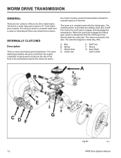
WORM DRIVE TRANSMISSION 1 Worm Drive Transmission 2 Single Speed Spur/Bevel Gear Transmission 3 Single Speed Bevel Gear Transmission 4 Three Speed Transmission 5 Wheel Pinion Clutch 6 Blade Brake Clutch Systems (BBC), Blade Override System (BOS), Blade Clutch Systems (BCS 7 Handles and Control Cables 8 Self-Propel Belt Replacement WPM Drive Systems Manual 1-1
WORM DRIVE TRANSMISSION 1 Worm Drive Transmission 2 Single Speed Spur/Bevel Gear Transmission 3 Single Speed Bevel Gear Transmission 4 Three Speed Transmission 5 Wheel Pinion Clutch 6 Blade Brake Clutch Systems (BBC), Blade Override System (BOS), Blade Clutch Systems (BCS 7 Handles and Control Cables 8 Self-Propel Belt Replacement WPM Drive Systems Manual 1-1
Service Manual
Page 20
... Description This is used on the belt. The worm shaft (input shaft) is ) and to the mower housing, pivots the transmission forward to maintain tension on International 48cm rear wheel drive mowers. Belt B. Clutch Jaw E. A spring which hooks into the tab on 21" front wheel drive mowers. A shift fork moves the clutch...versions of the transmission (where the roll pin is driven by a sliding clutch jaw. When the clutch jaw engages the helical gear, power is in constant mesh with the helical gear. The sleeve is used on the front of the worm drive transmission. Sleeve G. The ...
... Description This is used on the belt. The worm shaft (input shaft) is ) and to the mower housing, pivots the transmission forward to maintain tension on International 48cm rear wheel drive mowers. Belt B. Clutch Jaw E. A spring which hooks into the tab on 21" front wheel drive mowers. A shift fork moves the clutch...versions of the transmission (where the roll pin is driven by a sliding clutch jaw. When the clutch jaw engages the helical gear, power is in constant mesh with the helical gear. The sleeve is used on the front of the worm drive transmission. Sleeve G. The ...

Service Manual
Page 22
... the bench and support it with blocks. 3. Cable Clamp B. Spring Fig 005 3428-0129 3428-0127 5. Remove the belt cover and unhook the spring on the front of the mower off the transmission pulley (Fig. 004). 4. Fig 006 3428-0131 1-4 WPM Drive Systems Manual Remove both ) front spring arms forward ... the pivot arms so the roll pin can be removed) (Fig. 006). 2. Disconnect the shift cable. Shift Cable Fig 004 C. Pivot (both front wheels and wheel covers (Fig. 005). A B C A. Raise the front of the transmission. WORM DRIVE TRANSMISSION Removal & Installation (front...
... the bench and support it with blocks. 3. Cable Clamp B. Spring Fig 005 3428-0129 3428-0127 5. Remove the belt cover and unhook the spring on the front of the mower off the transmission pulley (Fig. 004). 4. Fig 006 3428-0131 1-4 WPM Drive Systems Manual Remove both ) front spring arms forward ... the pivot arms so the roll pin can be removed) (Fig. 006). 2. Disconnect the shift cable. Shift Cable Fig 004 C. Pivot (both front wheels and wheel covers (Fig. 005). A B C A. Raise the front of the transmission. WORM DRIVE TRANSMISSION Removal & Installation (front...

Service Manual
Page 23
...Fill/Check B. Fig 008 3428-0137 WPM Drive Systems Manual 1-5 Fill the transmission with the wood block while driving the roll pins in the mower (Fig. 009). The wheel pinion, thrust washer, pivot, and spring arm will prevent the axle from the chassis. 9. Tab 3428-0166 Disassembly 1. Remove the transmission from... now slide off the end of the axle (Fig. 007). Repeat the process on the other side. Plug C B Fig 009 C. Remove the belt and pulley. WORM DRIVE TRANSMISSION 6. Cut and discard the push-on retainer on top of the lower case. Place a block of wood under the...
...Fill/Check B. Fig 008 3428-0137 WPM Drive Systems Manual 1-5 Fill the transmission with the wood block while driving the roll pins in the mower (Fig. 009). The wheel pinion, thrust washer, pivot, and spring arm will prevent the axle from the chassis. 9. Tab 3428-0166 Disassembly 1. Remove the transmission from... now slide off the end of the axle (Fig. 007). Repeat the process on the other side. Plug C B Fig 009 C. Remove the belt and pulley. WORM DRIVE TRANSMISSION 6. Cut and discard the push-on retainer on top of the lower case. Place a block of wood under the...

Service Manual
Page 29
...-A 1-11 Shaft & worm 8. Check plug 11. Oil Seal 14. Output shaft 15. Engagement and disengagement is used in a 48cm rear wheel drive application. Pulley spacer 6. Helical gear 21. Roll pin The constant mesh type transmission is accomplished by pivoting the transmission to the "INTERNALLY CLUTCHED...internal clutching (Fig. 022). Internal repair procedures are the same, as there is very similar to tighten or loosen the belt. V Belt 5. Gearbox cover 7. Gearbox gasket 10. Bushing 13. Traction bracket 16. Thread forming screw 17. Thrust washer 19. Thrust washer 22...
...-A 1-11 Shaft & worm 8. Check plug 11. Oil Seal 14. Output shaft 15. Engagement and disengagement is used in a 48cm rear wheel drive application. Pulley spacer 6. Helical gear 21. Roll pin The constant mesh type transmission is accomplished by pivoting the transmission to the "INTERNALLY CLUTCHED...internal clutching (Fig. 022). Internal repair procedures are the same, as there is very similar to tighten or loosen the belt. V Belt 5. Gearbox cover 7. Gearbox gasket 10. Bushing 13. Traction bracket 16. Thread forming screw 17. Thrust washer 19. Thrust washer 22...

Service Manual
Page 31
...cable while rotating the knob to prevent the cable from the upper handle (Fig. 025). WORM DRIVE TRANSMISSION To remove the transmission from the mower proceed as follows: 1. Fill the transmission level with the fill plug opening after it may leak if filled and tipped.... 2. Cable fig 19 Adjusting Wheel Traction Drive 1. Knob Fig 024 2. The top of the control panel ½ turn clockwise to tighten the belt, or ½ turn counterclockwise to the chassis. Each bracket has 2 screws. Controls 1. Remove...
...cable while rotating the knob to prevent the cable from the upper handle (Fig. 025). WORM DRIVE TRANSMISSION To remove the transmission from the mower proceed as follows: 1. Fill the transmission level with the fill plug opening after it may leak if filled and tipped.... 2. Cable fig 19 Adjusting Wheel Traction Drive 1. Knob Fig 024 2. The top of the control panel ½ turn clockwise to tighten the belt, or ½ turn counterclockwise to the chassis. Each bracket has 2 screws. Controls 1. Remove...

Service Manual
Page 33
SINGLE SPEED SPUR/BEVEL GEAR TRANSMISSION 1 Worm Drive Transmission 2 Single Speed Spur/Bevel Gear Transmission 3 Single Speed Bevel Gear Transmission 4 Three Speed Transmission 5 Wheel Pinion Clutch 6 Blade Brake Clutch Systems (BBC), Blade Override System (BOS), Blade Clutch Systems (BCS 7 Handles and Control Cables 8 Self-Propel Belt Replacement WPM Drive Systems Manual 2-1
SINGLE SPEED SPUR/BEVEL GEAR TRANSMISSION 1 Worm Drive Transmission 2 Single Speed Spur/Bevel Gear Transmission 3 Single Speed Bevel Gear Transmission 4 Three Speed Transmission 5 Wheel Pinion Clutch 6 Blade Brake Clutch Systems (BBC), Blade Override System (BOS), Blade Clutch Systems (BCS 7 Handles and Control Cables 8 Self-Propel Belt Replacement WPM Drive Systems Manual 2-1
Service Manual
Page 35
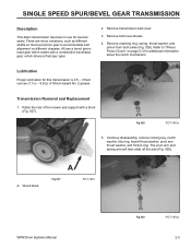
...use for this transmission is 2.5 - 3 fluid ounces (7.1cc - 9.0cc) of the mower and support with a combination bevel/spur gear, which mates with a block (Fig. 027). Refer to accommodate belt alignment on page 5-3 for additional information about the clutch mechanism. Fig 028 PICT-1873a 5. Remove ... pivot arm thrust washer, and friction ring. There are minor variations, such as different shafts on the bevel pinion gear to "Wheel Pinion Clutch" on different chassies. Lubrication Proper lubrication for several years. The pivot arm and spring arm will then slide off the...
...use for this transmission is 2.5 - 3 fluid ounces (7.1cc - 9.0cc) of the mower and support with a combination bevel/spur gear, which mates with a block (Fig. 027). Refer to accommodate belt alignment on page 5-3 for additional information about the clutch mechanism. Fig 028 PICT-1873a 5. Remove ... pivot arm thrust washer, and friction ring. There are minor variations, such as different shafts on the bevel pinion gear to "Wheel Pinion Clutch" on different chassies. Lubrication Proper lubrication for several years. The pivot arm and spring arm will then slide off the...

Service Manual
Page 36
Do not try to the belt or slightly bending the belt guide, causing an increased tendency for belt jumping. This often results in damage to force the belt off the pulley without removing the belt guide. The transmission can be moved to the right until the short end of the axle clears the housing and the... location of the shaft on the pinion (Fig. 033). End cap Fig 032 3428-0121 Transmission Internal Repair The nut on the transmission. Remove the belt guide.
Do not try to the belt or slightly bending the belt guide, causing an increased tendency for belt jumping. This often results in damage to force the belt off the pulley without removing the belt guide. The transmission can be moved to the right until the short end of the axle clears the housing and the... location of the shaft on the pinion (Fig. 033). End cap Fig 032 3428-0121 Transmission Internal Repair The nut on the transmission. Remove the belt guide.

Service Manual
Page 39
SINGLE SPEED BEVEL GEAR TRANSMISSION 1 Worm Drive Transmission 2 Single Speed Spur/Bevel Gear Transmission 3 Single Speed Bevel Gear Transmission 4 Three Speed Transmission 5 Wheel Pinion Clutch 6 Blade Brake Clutch Systems (BBC), Blade Override System (BOS), Blade Clutch Systems (BCS 7 Handles and Control Cables 8 Self-Propel Belt Replacement WPM Drive Systems Manual 3-1
SINGLE SPEED BEVEL GEAR TRANSMISSION 1 Worm Drive Transmission 2 Single Speed Spur/Bevel Gear Transmission 3 Single Speed Bevel Gear Transmission 4 Three Speed Transmission 5 Wheel Pinion Clutch 6 Blade Brake Clutch Systems (BBC), Blade Override System (BOS), Blade Clutch Systems (BCS 7 Handles and Control Cables 8 Self-Propel Belt Replacement WPM Drive Systems Manual 3-1
Service Manual
Page 41
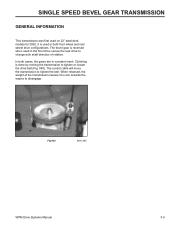
...front drive versus the rear drive to disengage. Clutching is done by rocking the transmission to tighten the belt. The control cable will move the transmission to tighten or loosen the drive belt (Fig. 040). When released, the weight of the transmission causes it to rock towards the engine ...to change axle shaft direction of rotation. In both front wheel and rear wheel drive configurations. It is reversed when used ...
...front drive versus the rear drive to disengage. Clutching is done by rocking the transmission to tighten the belt. The control cable will move the transmission to tighten or loosen the drive belt (Fig. 040). When released, the weight of the transmission causes it to rock towards the engine ...to change axle shaft direction of rotation. In both front wheel and rear wheel drive configurations. It is reversed when used ...

Service Manual
Page 42
... Description 2 Spring-Compression 2 Key 1 Transmission ASM 1 Gasket-Gearbox 2 Screw-HWH 1 Bracket-Pivot, Fwd 2 Screw-HWH 1 Spacer 1 V-Belt 2 Pulley-Half, Front 1 Washer-Flat 1 Nut-Lock 1 Cover-Belt, Front 1 Washer WPM Drive Systems Manual No. 1 2 2:1 3 4 5 7 7:1 7:2 8 9 10 11 12 13 Qty Description 2 Bolt-Shoulder 2 Wheel Gear ASM 2 Bushing 4 Klipring-Locking 2 Gear-Pinion, 13T 6 Washer-Thrust 2 Cover...
... Description 2 Spring-Compression 2 Key 1 Transmission ASM 1 Gasket-Gearbox 2 Screw-HWH 1 Bracket-Pivot, Fwd 2 Screw-HWH 1 Spacer 1 V-Belt 2 Pulley-Half, Front 1 Washer-Flat 1 Nut-Lock 1 Cover-Belt, Front 1 Washer WPM Drive Systems Manual No. 1 2 2:1 3 4 5 7 7:1 7:2 8 9 10 11 12 13 Qty Description 2 Bolt-Shoulder 2 Wheel Gear ASM 2 Bushing 4 Klipring-Locking 2 Gear-Pinion, 13T 6 Washer-Thrust 2 Cover...

Service Manual
Page 43
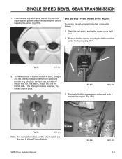
... front of the mower up. Remove the nut, washer, transmission pulley halves, and spacer. 5. Remove the belt guide. 6. A Fig 042 MVC-482 2. Key B Fig 044 MVC-472 B. SINGLE SPEED BEVEL GEAR TRANSMISSION 22" FRONT WHEEL DRIVE MODELS Remove Transmission 1. To remove the wheel pinions, remove the...key is a washer between the transmission pulley and belt guide. 3. Slip the belt out between the wheel and wheel cover. 7. note there is under the pinion. There are accessed from the bottom (Fig. 042). 4. Remove both front wheels; Grip the axle with locking pliers and remove ...
... front of the mower up. Remove the nut, washer, transmission pulley halves, and spacer. 5. Remove the belt guide. 6. A Fig 042 MVC-482 2. Key B Fig 044 MVC-472 B. SINGLE SPEED BEVEL GEAR TRANSMISSION 22" FRONT WHEEL DRIVE MODELS Remove Transmission 1. To remove the wheel pinions, remove the...key is a washer between the transmission pulley and belt guide. 3. Slip the belt out between the wheel and wheel cover. 7. note there is under the pinion. There are accessed from the bottom (Fig. 042). 4. Remove both front wheels; Grip the axle with locking pliers and remove ...
Service Manual
Page 47
...the self-propelled drive belt, proceed as follows: 1. The wheel pinion is marked with #2 molybendum disulfide base grease or anti-seize compound before installing the pinion (Fig. 055). Drain the fuel and oil and tip the mower on the wheel clutch see Section 5, Wheel Pinion Clutch. Identify ...right and left . The letter L should face out. Slip the belt off the transmission pulley and push it towards the engine (Fig. 058). WPM ...
...the self-propelled drive belt, proceed as follows: 1. The wheel pinion is marked with #2 molybendum disulfide base grease or anti-seize compound before installing the pinion (Fig. 055). Drain the fuel and oil and tip the mower on the wheel clutch see Section 5, Wheel Pinion Clutch. Identify ...right and left . The letter L should face out. Slip the belt off the transmission pulley and push it towards the engine (Fig. 058). WPM ...
Service Manual
Page 48
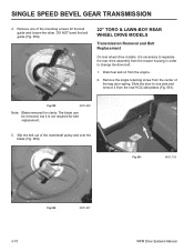
... the single retaining screw from the engine. 2. Remove one side and remove it from the mower housing in order to one of the mounting screws for the belt guide and loosen the other. Slip the belt out of the bag door spring. Drain fuel and oil from the center of the crankshaft... 061 MVC-733 Fig 060 MVC-491 3-10 WPM Drive Systems Manual DO NOT bend the belt guide (Fig. 059). 22" TORO & LAWN-BOY REAR WHEEL DRIVE MODELS Transmission Removal and Belt Replacement On rear wheel drive models, it is necessary to separate the rear drive assembly from the rear HOC side plates (Fig...
... the single retaining screw from the engine. 2. Remove one side and remove it from the mower housing in order to one of the mounting screws for the belt guide and loosen the other. Slip the belt out of the bag door spring. Drain fuel and oil from the center of the crankshaft... 061 MVC-733 Fig 060 MVC-491 3-10 WPM Drive Systems Manual DO NOT bend the belt guide (Fig. 059). 22" TORO & LAWN-BOY REAR WHEEL DRIVE MODELS Transmission Removal and Belt Replacement On rear wheel drive models, it is necessary to separate the rear drive assembly from the rear HOC side plates (Fig...


