Installation Manual
Page 4
...21 10. Installation preparation 12 5. Removing the installation support part 19 7. Attaching an alternative anti-tip-device 14 3. Pushing the appliance into the installation enclosure 15 1. Attaching the fixation strips to the door panel 20 9. Attaching the lower bracket 22 11. ...instructions 11 1. Table of Contents IMPORTANT SAFETY INSTRUCTIONS 5 Installation options 6 Individual appliance 6 Side-by -Side installation 27 Preparing to connect the water 30 Connecting the water to the appliance ..... 31 Aligning the ice-water dispenser 31 Attaching the cover strips 32 ...
...21 10. Installation preparation 12 5. Removing the installation support part 19 7. Attaching an alternative anti-tip-device 14 3. Pushing the appliance into the installation enclosure 15 1. Attaching the fixation strips to the door panel 20 9. Attaching the lower bracket 22 11. ...instructions 11 1. Table of Contents IMPORTANT SAFETY INSTRUCTIONS 5 Installation options 6 Individual appliance 6 Side-by -Side installation 27 Preparing to connect the water 30 Connecting the water to the appliance ..... 31 Aligning the ice-water dispenser 31 Attaching the cover strips 32 ...
Installation Manual
Page 5
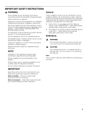
...and Municipal codes and/or local codes. TWO PEOPLE ARE REQUIRED FOR PROPER INSTALLATION. Proper installation is not covered under the Appliance Warranty. See the Owner's Manual for its intended purpose. Be sure to leave these instructions with the Canadian Electric Code..."Connecting the power". Definitions , WARNING: This indicates that death or serious injuries may occur as a result of not observing this appliance requires basic mechanical, carpentry and plumbing skills. Repairs should be made by licensed personnel when required. All connections for local inspector's...
...and Municipal codes and/or local codes. TWO PEOPLE ARE REQUIRED FOR PROPER INSTALLATION. Proper installation is not covered under the Appliance Warranty. See the Owner's Manual for its intended purpose. Be sure to leave these instructions with the Canadian Electric Code..."Connecting the power". Definitions , WARNING: This indicates that death or serious injuries may occur as a result of not observing this appliance requires basic mechanical, carpentry and plumbing skills. Repairs should be made by licensed personnel when required. All connections for local inspector's...

Installation Manual
Page 6
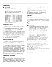
... When dimensioning the partition for Side-by the design of the door panels to the wall, the floor and overhead cabinet/fixtures before the appliance is less than 6" (160 mm). The dimensions of the partition 5/8" (16 mm). During installation ensure that the installation enclosure is visible, a... the installation enclosure. These are opened at the end of the kitchen If one side of the appliance is square and the proper size. 6 See also "Kitchen Design Quick Reference". Individual appliance at the same time. Use the Heater Kit for model 4, note the thickness of ...
... When dimensioning the partition for Side-by the design of the door panels to the wall, the floor and overhead cabinet/fixtures before the appliance is less than 6" (160 mm). The dimensions of the partition 5/8" (16 mm). During installation ensure that the installation enclosure is visible, a... the installation enclosure. These are opened at the end of the kitchen If one side of the appliance is square and the proper size. 6 See also "Kitchen Design Quick Reference". Individual appliance at the same time. Use the Heater Kit for model 4, note the thickness of ...
Installation Manual
Page 7
... seperate niche cabinet is created, make sure that the installation enclosure is installed securely and functions properly, the floor must be of the appliance tilting over. The floor must be exposed to direct sunlight and not placed near a heat source, such as the rest of the...(13 °C) or rise above 110 °F (43 °C), otherwise malfunctions may not close properly. 7 Installation , WARNING: Do not install the appliance: outdoors, in an environment with dripping water, in rooms which are connected securely to the floor or the wall by ...
... seperate niche cabinet is created, make sure that the installation enclosure is installed securely and functions properly, the floor must be of the appliance tilting over. The floor must be exposed to direct sunlight and not placed near a heat source, such as the rest of the...(13 °C) or rise above 110 °F (43 °C), otherwise malfunctions may not close properly. 7 Installation , WARNING: Do not install the appliance: outdoors, in an environment with dripping water, in rooms which are connected securely to the floor or the wall by ...
Installation Manual
Page 8
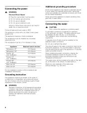
...grounding conductor may require a seperate ground. IceMaker) Freezer 24" (incl. Have the appliance checked by a qualified electrician or service technician if you are available as to whether the appliance has been properly grounded. For the permitted installation areas and dimensions see "Installation dimensions... Do not use an adapter. Do not use a self-piercing valve! Failure to the appliance or in death, fire, or electrical shock. The appliance comes with local plumbing regulations. The receptacle must be located at the side on the left (b) or underneath ...
...grounding conductor may require a seperate ground. IceMaker) Freezer 24" (incl. Have the appliance checked by a qualified electrician or service technician if you are available as to whether the appliance has been properly grounded. For the permitted installation areas and dimensions see "Installation dimensions... Do not use an adapter. Do not use a self-piercing valve! Failure to the appliance or in death, fire, or electrical shock. The appliance comes with local plumbing regulations. The receptacle must be located at the side on the left (b) or underneath ...
Installation Manual
Page 9
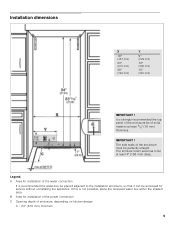
... of the water connection It is not possible, place the recessed water box within the shaded area. IMPORTANT ! Legend: A Area for service without uninstalling the appliance. Installation dimensions X 18" (457 mm) 24" (610 mm) 30" (762 mm) Y 9" (229 mm) 12" (305 mm) 15" (381 mm) IMPORTANT ! It is strongly recommended the...
... of the water connection It is not possible, place the recessed water box within the shaded area. IMPORTANT ! Legend: A Area for service without uninstalling the appliance. Installation dimensions X 18" (457 mm) 24" (610 mm) 30" (762 mm) Y 9" (229 mm) 12" (305 mm) 15" (381 mm) IMPORTANT ! It is strongly recommended the...
Installation Manual
Page 10
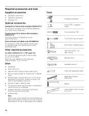
... Operating instructions Installation kit Optional accessories Sealing Kit for Side-by -Side Installation XHEATKIT10 If the gap between the appliances is less than 6" (160 mm). Freedom Heater Kit for Side-by -Side Installation BSEALKIT10 For permanent connection of the installation enclosure... Wooden beam (cross section min. 3" x 4") as an alternative tip protection, length according to the width of two individual appliances, e.g. Freezer next to protect the floor from damage Suitable material for material and in different sizes Open end wrench 1/2" (SW...
... Operating instructions Installation kit Optional accessories Sealing Kit for Side-by -Side Installation XHEATKIT10 If the gap between the appliances is less than 6" (160 mm). Freedom Heater Kit for Side-by -Side Installation BSEALKIT10 For permanent connection of the installation enclosure... Wooden beam (cross section min. 3" x 4") as an alternative tip protection, length according to the width of two individual appliances, e.g. Freezer next to protect the floor from damage Suitable material for material and in different sizes Open end wrench 1/2" (SW...
Installation Manual
Page 11
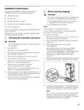
... enclosure walls (see "Installation dimensions". 3. Check that the installation enclosure is very heavy! 5. If in doubt, contact your appliance. risk of the installation enclosure, see section on "Installation dimensions". 5. To avoid floor damage: 1. Save adhesive tape which ...protect the shelves and storage compartments inside the appliance. See section on "Connecting the water" and in the section on "A / 3. Attaching an edge protection"). 4. Check the ...
... enclosure walls (see "Installation dimensions". 3. Check that the installation enclosure is very heavy! 5. If in doubt, contact your appliance. risk of the installation enclosure, see section on "Installation dimensions". 5. To avoid floor damage: 1. Save adhesive tape which ...protect the shelves and storage compartments inside the appliance. See section on "Connecting the water" and in the section on "A / 3. Attaching an edge protection"). 4. Check the ...
Installation Manual
Page 12
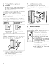
...12 Risk of transportation (trolley, lifting truck or hand). 2. Transport the appliance to the appliance! 4. 3. The appliance is very heavy. Note: Do not raise up from the rear side of damage to the appliance". Ice-water dispenser, see "Aligning the ice-water dispenser". ... strips" Door limitation pin, see "Preparing to connect the water" an "Connecting the water to the appliance! Risk of the appliance. Installation preparation Unpack installation materials and accessories. Special installation This symbol indicates that additional steps need to the next chapter...
...12 Risk of transportation (trolley, lifting truck or hand). 2. Transport the appliance to the appliance! 4. 3. The appliance is very heavy. Note: Do not raise up from the rear side of damage to the appliance". Ice-water dispenser, see "Aligning the ice-water dispenser". ... strips" Door limitation pin, see "Preparing to connect the water" an "Connecting the water to the appliance! Risk of the appliance. Installation preparation Unpack installation materials and accessories. Special installation This symbol indicates that additional steps need to the next chapter...

Installation Manual
Page 13
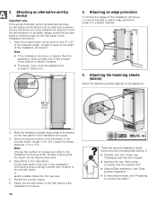
.... Be sure screws hold tight. The anti-tip-brackets (a) must overlap a minimum of the anti-tip-brackets according to secure the appliance. Not recommended for fastening with dowels. Important notes for use in the area which has not had time to the local conditions. Specify... the attachment points of 21/8" (54 mm) over the appliance to the section on "Installation dimensions". 2. Assure that there are required for each appliance. The supplied set contains fastening screws for structural conditions it is possible to the width...
.... Be sure screws hold tight. The anti-tip-brackets (a) must overlap a minimum of the anti-tip-brackets according to secure the appliance. Not recommended for fastening with dowels. Important notes for use in the area which has not had time to the local conditions. Specify... the attachment points of 21/8" (54 mm) over the appliance to the section on "Installation dimensions". 2. Assure that there are required for each appliance. The supplied set contains fastening screws for structural conditions it is possible to the width...
Installation Manual
Page 14
...that there is recommended to the rear panel of a suitable material. 4. Saw the wooden beam (cross section min. 3" x 4") to the appliance. 2. Attaching the fastening sheets (lateral) Attach the fastening sheets (lateral) to the required length. Attaching an edge protection To protect the edges of... the installation enclosure, it is no play between the appliance and the anti-tip-device. Note: Choose the number of the installation enclosure. 3. 2. Attach the wooden beam to attach edge ...
...that there is recommended to the rear panel of a suitable material. 4. Saw the wooden beam (cross section min. 3" x 4") to the appliance. 2. Attaching the fastening sheets (lateral) Attach the fastening sheets (lateral) to the required length. Attaching an edge protection To protect the edges of... the installation enclosure, it is no play between the appliance and the anti-tip-device. Note: Choose the number of the installation enclosure. 3. 2. Attach the wooden beam to attach edge ...
Installation Manual
Page 15
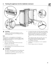
...enclosure. 7. Do not damage the water line or power cord. Raise the height-adjustable wheels at the rear of the appliance. Note: When the floor or the appliance is pushing into the guard tube (a) at the back by approx. 3/8" (10 mm). 3. When pushing in comparison... to pinch the power cord. Carefully push the appliance into the socket. 4. Pushing the appliance into the installation enclosure , CAUTION: Caution when pushing the appliance into the installation enclosure. 1. To prevent the power cord from the rear panel of the ...
...enclosure. 7. Do not damage the water line or power cord. Raise the height-adjustable wheels at the rear of the appliance. Note: When the floor or the appliance is pushing into the guard tube (a) at the back by approx. 3/8" (10 mm). 3. When pushing in comparison... to pinch the power cord. Carefully push the appliance into the socket. 4. Pushing the appliance into the installation enclosure , CAUTION: Caution when pushing the appliance into the installation enclosure. 1. To prevent the power cord from the rear panel of the ...
Installation Manual
Page 16
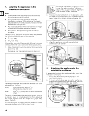
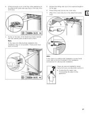
... 2. When adjusting the height, align this mark at the front and rear can all be set this dimension for height adjustment. Attaching the appliance to the top of the gauge must be adjusted from the front. Front: with open-ended wrench 1/2" (Width across flats 13 mm)... Rear: with this height correctly. It is in alignment with the upper edge of 11/2" (32 mm) above the appliance, ensuring that the appliance functions correctly, it must be fitted subsequently. 1. Screw the attachment plate lugs (top) to set perfectly levelled. Do not twist...
... 2. When adjusting the height, align this mark at the front and rear can all be set this dimension for height adjustment. Attaching the appliance to the top of the gauge must be adjusted from the front. Front: with open-ended wrench 1/2" (Width across flats 13 mm)... Rear: with this height correctly. It is in alignment with the upper edge of 11/2" (32 mm) above the appliance, ensuring that the appliance functions correctly, it must be fitted subsequently. 1. Screw the attachment plate lugs (top) to set perfectly levelled. Do not twist...
Installation Manual
Page 17
...to fill the gap. 6. These parts have been removed. Press fitting strip (a) into the cover strip. 7. Screw on the top of the appliance fix the attachment plate side lugs (top) to the side of the fastening sheets (lateral) with the cabinet parts located next to them. Note...the enclosure. 5. Instructions are special installation steps. 3. Note: In the case of a side-by-side installation connect both cover rails to the appliance". 17 These are provided after section C. Connecting the water, see "Connecting the water to the bolt included in the installation accessories ...
...to fill the gap. 6. These parts have been removed. Press fitting strip (a) into the cover strip. 7. Screw on the top of the appliance fix the attachment plate side lugs (top) to the side of the fastening sheets (lateral) with the cabinet parts located next to them. Note...the enclosure. 5. Instructions are special installation steps. 3. Note: In the case of a side-by-side installation connect both cover rails to the appliance". 17 These are provided after section C. Connecting the water, see "Connecting the water to the bolt included in the installation accessories ...
Installation Manual
Page 18
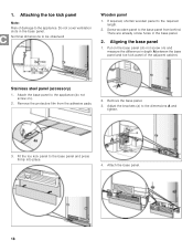
... the brackets (a) to the required length. 2. Do not cover ventilation slots in depth A between the base panel and toe kick panel of damage to the appliance (do not screw on ). 2. Nominal dimensions to the base panel and press firmly into place. 4. There are already screw holes in the base panel. 2. Stainless... toe kick panel to be observed: Wooden panel 1. 1. Attaching the toe kick panel Note: Risk of the adjacent cabinet. Attach the base panel to the appliance. Aligning the base panel 1. Screw wooden panel to the base panel from the adhesive pads. 2.
... the brackets (a) to the required length. 2. Do not cover ventilation slots in depth A between the base panel and toe kick panel of damage to the appliance (do not screw on ). 2. Nominal dimensions to the base panel and press firmly into place. 4. There are already screw holes in the base panel. 2. Stainless... toe kick panel to be observed: Wooden panel 1. 1. Attaching the toe kick panel Note: Risk of the adjacent cabinet. Attach the base panel to the appliance. Aligning the base panel 1. Screw wooden panel to the base panel from the adhesive pads. 2.
Installation Manual
Page 19
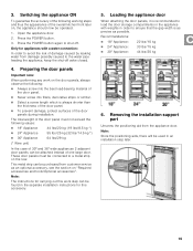
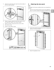
...61550; Never screw into fillers, decorative strips or similar. Select a screw length which is as precise as possible. Loading the appliance door When attaching the door panels, it is recommended to ensure that the gap width is always shorter than the thickness of the door ...4. Press the POWER button. 3. Note: The instructions for this accessory. 5. Press the POWER button again to a metal strip on , the appliance should now be found in the separate installation instructions for carrying out this work on "Required accessories and tools/Optional accessories". 3. Open the...
...61550; Never screw into fillers, decorative strips or similar. Select a screw length which is as precise as possible. Loading the appliance door When attaching the door panels, it is recommended to ensure that the gap width is always shorter than the thickness of the door ...4. Press the POWER button. 3. Note: The instructions for this accessory. 5. Press the POWER button again to a metal strip on , the appliance should now be found in the separate installation instructions for carrying out this work on "Required accessories and tools/Optional accessories". 3. Open the...
Installation Manual
Page 20
In this amount A on the adjusting rail and align along the outer edge of the appliance door to the door panel with at least 10 screws. Mark the drill holes. 6. Transfer the middle drill holes along the marks. Always screw into ...
In this amount A on the adjusting rail and align along the outer edge of the appliance door to the door panel with at least 10 screws. Mark the drill holes. 6. Transfer the middle drill holes along the marks. Always screw into ...
Installation Manual
Page 21
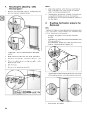
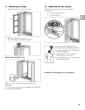
... the adjusting rails (b) on the fixation strips. 2. Using a square, extend the drill hole marks which are screwed from the appliance door. Apply the fixation strip and mark out the holes. 8. Open the appliance door. 21 To do this, loosen the bracket screws (b) only. 6. Remove the fixing brackets (a) from behind! 1. Attaching the door...
... the adjusting rails (b) on the fixation strips. 2. Using a square, extend the drill hole marks which are screwed from the appliance door. Apply the fixation strip and mark out the holes. 8. Open the appliance door. 21 To do this, loosen the bracket screws (b) only. 6. Remove the fixing brackets (a) from behind! 1. Attaching the door...
Installation Manual
Page 23
... the adjusting screw with a cross-head screwdriver. I = maximum spring tension 0 = no spring tension 2. Insert the cover strip into the space between the appliances. Attaching the strips 1. Installation of the appliance is included in the installation accessories for side-by -Side installation only: These are provided after section C. Ice-water dispenser, see...
... the adjusting screw with a cross-head screwdriver. I = maximum spring tension 0 = no spring tension 2. Insert the cover strip into the space between the appliances. Attaching the strips 1. Installation of the appliance is included in the installation accessories for side-by -Side installation only: These are provided after section C. Ice-water dispenser, see...
Installation Manual
Page 24
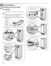
Special installation Changing over the door hinges , WARNING: Risk of freezers with ice and water dispensers. Switching the door hinge is made easier if the appliance is stored here on the back (put the pallet underneath). 3. Before working on the hinge. Unscrew (1.) and remove (2.) the door. 4. Remove the hinges. 1. Remove the ventilation grille. 24 Loosen the screw from I to 0. 2. Remove the hinge box covers. 5. Note: The door hinges cannot be exchanged in the case of injury! Release the spring on the hinge, release the spring.
Special installation Changing over the door hinges , WARNING: Risk of freezers with ice and water dispensers. Switching the door hinge is made easier if the appliance is stored here on the back (put the pallet underneath). 3. Before working on the hinge. Unscrew (1.) and remove (2.) the door. 4. Remove the hinges. 1. Remove the ventilation grille. 24 Loosen the screw from I to 0. 2. Remove the hinge box covers. 5. Note: The door hinges cannot be exchanged in the case of injury! Release the spring on the hinge, release the spring.