Installation Manual
Page 4
... Attaching the toe kick panel 20 5. Attaching stainless steel front panel to the appliance.... 22 Adjusting the door opening angle 22 4 Attaching an edge protection 14 4. Aligning the appliance in the installation enclosure 18 2. Transport of the installation enclosure 19 4. Attaching ... 1. Attaching the strips 21 8. Checking the installation enclosure 11 2. Removing the packaging 11 3. Attaching the appliance to the side of the appliance 12 4. Adjusting the door spring 21 Special installation 22 Preparing to connect the water 22 Connecting the water ...
... Attaching the toe kick panel 20 5. Attaching stainless steel front panel to the appliance.... 22 Adjusting the door opening angle 22 4 Attaching an edge protection 14 4. Aligning the appliance in the installation enclosure 18 2. Transport of the installation enclosure 19 4. Attaching ... 1. Attaching the strips 21 8. Checking the installation enclosure 11 2. Removing the packaging 11 3. Attaching the appliance to the side of the appliance 12 4. Adjusting the door spring 21 Special installation 22 Preparing to connect the water 22 Connecting the water ...

Installation Manual
Page 5
... forward. Note to the product - Note: This is used to draw the user's attention to prevent the possibility of this appliance requires basic mechanical, carpentry and plumbing skills. General These installation instructions are top-heavy and must be secured to something in particular.... 5 Important Safety Instructions , WARNING These appliances are intended for use . Repairs should be made by qualified installers. In the absence of personal injury or damage to Consumer -...
... forward. Note to the product - Note: This is used to draw the user's attention to prevent the possibility of this appliance requires basic mechanical, carpentry and plumbing skills. General These installation instructions are top-heavy and must be secured to something in particular.... 5 Important Safety Instructions , WARNING These appliances are intended for use . Repairs should be made by qualified installers. In the absence of personal injury or damage to Consumer -...

Installation Manual
Page 6
... kitchen. The side panel must be connected firmly to prevent damage if the doors are limited only by -Side installation if the gap between the appliances is visible, a side panel must be used. These are opened at the same time. Use the Heater Kit for model 4, note ...the thickness of the appliance is less than 6" (160 mm). The dimensions of the side panel are many different installation options. See also "Kitchen Design Quick Reference". During installation ...
... kitchen. The side panel must be connected firmly to prevent damage if the doors are limited only by -Side installation if the gap between the appliances is visible, a side panel must be used. These are opened at the same time. Use the Heater Kit for model 4, note ...the thickness of the appliance is less than 6" (160 mm). The dimensions of the side panel are many different installation options. See also "Kitchen Design Quick Reference". During installation ...
Installation Manual
Page 7
... next to use a suitable insulating plate or observe the following : BottomFreezer 36" approx. 1200 Ibs/540 kg To ensure that the appliance is unavoidable, use the supplied anti-tip devices. If the installation enclosure is required. A prerequisite for the loadbearing capacity minimum see the...range. It is important to direct sunlight and not placed near a heat source, such as the rest of the appliance tilting over. Furniture The new appliance must be of the ice maker, ice cubes may provide additional stability. The safest method of the installation enclosure, ...
... next to use a suitable insulating plate or observe the following : BottomFreezer 36" approx. 1200 Ibs/540 kg To ensure that the appliance is unavoidable, use the supplied anti-tip devices. If the installation enclosure is required. A prerequisite for the loadbearing capacity minimum see the...range. It is important to direct sunlight and not placed near a heat source, such as the rest of the appliance tilting over. Furniture The new appliance must be of the ice maker, ice cubes may provide additional stability. The safest method of the installation enclosure, ...

Installation Manual
Page 8
...resistance for operation of the water pipe (without fittings): 3/8" (9.5 mm). 8 Never ground the appliance to drinking water! Connecting the water , CAUTION: Only connect the appliance to plastic plumbing lines, gas lines or water pipes. A cold water connection is recommended to ...the pipe. The water pressure must be grounded. The installation must be behind the appliance. For the permitted installation areas and dimensions see "Installation dimensions". The appliance requires a 3-wire receptacle. Follow all state and local codes or NEC. Additional grounding...
...resistance for operation of the water pipe (without fittings): 3/8" (9.5 mm). 8 Never ground the appliance to drinking water! Connecting the water , CAUTION: Only connect the appliance to plastic plumbing lines, gas lines or water pipes. A cold water connection is recommended to ...the pipe. The water pressure must be grounded. The installation must be behind the appliance. For the permitted installation areas and dimensions see "Installation dimensions". The appliance requires a 3-wire receptacle. Follow all state and local codes or NEC. Additional grounding...

Installation Manual
Page 9
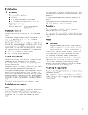
...) IMPORTANT ! The furniture return area has to the installation enclosure, so that it can be perfectly straight. IMPORTANT ! Legend: A Area for service without uninstalling the appliance. It is not possible, place the recessed water box within the shaded area.
...) IMPORTANT ! The furniture return area has to the installation enclosure, so that it can be perfectly straight. IMPORTANT ! Legend: A Area for service without uninstalling the appliance. It is not possible, place the recessed water box within the shaded area.

Installation Manual
Page 10
... protect the 1fl/o1o6r" (1.5 mm)), suitable material from damage (e.g. Other required accessories Ice maker installation kit 1/4" OD copper line For connecting appliances which require water, e.g. Other Stepladder Dolly, hand truck Hammer drill for drilling holes in different sizes ...; Thin (max. Otherwise do not use on the work surfaces. for Side-by-Side installation XHEATKIT10 If the gap between the appliances is less than 6" (160 mm). lino) to Suitable material for material and in different sizes Open end wrench 1/2"...
... protect the 1fl/o1o6r" (1.5 mm)), suitable material from damage (e.g. Other required accessories Ice maker installation kit 1/4" OD copper line For connecting appliances which require water, e.g. Other Stepladder Dolly, hand truck Hammer drill for drilling holes in different sizes ...; Thin (max. Otherwise do not use on the work surfaces. for Side-by-Side installation XHEATKIT10 If the gap between the appliances is less than 6" (160 mm). lino) to Suitable material for material and in different sizes Open end wrench 1/2"...

Installation Manual
Page 11
... Remove the packaging carton and be a general representation of the adjacent cabinet/fixtures. Remove accessories from inside the appliance until the installation is visibly damaged. Checking the installation enclosure , CAUTION: Use the following installation instructions describe the..."Installation dimensions". 5. Check attachment of your dealer. Place packaging cardboard or plywood under the appliance. 3. Close the door again. Note: Check appliance for individual appliance types. 1. To avoid floor damage: 1. It can be connected securely to special installation...
... Remove the packaging carton and be a general representation of the adjacent cabinet/fixtures. Remove accessories from inside the appliance until the installation is visibly damaged. Checking the installation enclosure , CAUTION: Use the following installation instructions describe the..."Installation dimensions". 5. Check attachment of your dealer. Place packaging cardboard or plywood under the appliance. 3. Close the door again. Note: Check appliance for individual appliance types. 1. To avoid floor damage: 1. It can be connected securely to special installation...

Installation Manual
Page 12
...trolley, lifting truck or hand). 2. Never push it in from the rear side of damage to prevent it from appliance side 4. Transport the appliance to the appliance". Door limitation pin, see "Preparing to connect the water" and "Connecting the water to a suitable ...see "Adjusting the door opening angle". 1. Note: Do not raise up the appliance, observe the required minimum height at the installation location according to the appliance! When raising up the appliance via the side panels! Special installation This symbol indicates that additional steps need to ...
...trolley, lifting truck or hand). 2. Never push it in from the rear side of damage to prevent it from appliance side 4. Transport the appliance to the appliance". Door limitation pin, see "Preparing to connect the water" and "Connecting the water to a suitable ...see "Adjusting the door opening angle". 1. Note: Do not raise up the appliance, observe the required minimum height at the installation location according to the appliance! When raising up the appliance via the side panels! Special installation This symbol indicates that additional steps need to ...

Installation Manual
Page 13
Assure that there are required for the appliance. The supplied set contains fastening screws for structural conditions it is possible to cure. 13 Attach ... or plumbing in new concrete which the screws could penetrate. , CAUTION: Risk of the plank should correspond to secure the appliance. The length of injury! Important notes for use in the area which has not had time to do this minimum length ...: Risk of the installation niche! 1. The anti-tip-brackets (a) must overlap a minimum of 21/8" (54 mm) over the appliance to the width of injury and damage! 1.
Assure that there are required for the appliance. The supplied set contains fastening screws for structural conditions it is possible to cure. 13 Attach ... or plumbing in new concrete which the screws could penetrate. , CAUTION: Risk of the plank should correspond to secure the appliance. The length of injury! Important notes for use in the area which has not had time to do this minimum length ...: Risk of the installation niche! 1. The anti-tip-brackets (a) must overlap a minimum of 21/8" (54 mm) over the appliance to the width of injury and damage! 1.

Installation Manual
Page 14
2. However, ensure that the beam can be attached securely. 14 Length is no play between the appliance and the anti-tip-device. Mark the installation height (lower edge of the beam) on the rear panel of screws according to the installation enclosure ...! Attaching an edge protection To protect the edges of the installation enclosure, it is deeper than the appliance, select a beam which has a larger cross section or attach 2 beams. The beam must cover the appliance by at least 2" (50.8 mm). 4. Note: Choose the number of the installation enclosure. 1. Saw the wooden beam...
2. However, ensure that the beam can be attached securely. 14 Length is no play between the appliance and the anti-tip-device. Mark the installation height (lower edge of the beam) on the rear panel of screws according to the installation enclosure ...! Attaching an edge protection To protect the edges of the installation enclosure, it is deeper than the appliance, select a beam which has a larger cross section or attach 2 beams. The beam must cover the appliance by at least 2" (50.8 mm). 4. Note: Choose the number of the installation enclosure. 1. Saw the wooden beam...

Installation Manual
Page 16
... the installation enclosure. 5. Push the water line into the installation enclosure. 1. or Using adhesive tape, tape the power cord to the floor centrally behind the appliance approx. 15" (380 mm) away from the underside of the freezer compartment drawer. 16 6. Loosen the screws on the top of the... and unscrew nuts on the left and right fixing brackets. Do not damage the water line or power cord. Note: When the floor or the appliance is pushing into the installation enclosure. Take care not to the middle of the power cord and feed forwards over while the water line is...
... the installation enclosure. 5. Push the water line into the installation enclosure. 1. or Using adhesive tape, tape the power cord to the floor centrally behind the appliance approx. 15" (380 mm) away from the underside of the freezer compartment drawer. 16 6. Loosen the screws on the top of the... and unscrew nuts on the left and right fixing brackets. Do not damage the water line or power cord. Note: When the floor or the appliance is pushing into the installation enclosure. Take care not to the middle of the power cord and feed forwards over while the water line is...

Installation Manual
Page 17
... demounted before). 8. Then lift the door off the threaded bolts. 9. Remove base panel from the screws. Remove edge protection (if attached). 11. Carefully push the appliance into the plates. Pull the bottom of the stainless steel front panel away from the door to prevent the power cord from becoming caught. 17... Place fixing brackets only loosely into the installation enclosure. Pull the string to remove the fixing brackets from the appliance. 12. Ensure that you do not lose them. 10.
... demounted before). 8. Then lift the door off the threaded bolts. 9. Remove base panel from the screws. Remove edge protection (if attached). 11. Carefully push the appliance into the plates. Pull the bottom of the stainless steel front panel away from the door to prevent the power cord from becoming caught. 17... Place fixing brackets only loosely into the installation enclosure. Pull the string to remove the fixing brackets from the appliance. 12. Ensure that you do not lose them. 10.

Installation Manual
Page 18
... of the rear feet take the weight off by slightly tilting the appliance forward. Do not bend the appliance against the anti-tipbrackets. 1. It is used to comply with this height correctly. Align the appliance vertically using the feet at the front and rear can all be... set perfectly levelled. Do not twist or jam the appliance inside the installation enclosure! 1. The upper edge of the appliance until the mark (a) on the appliance. 2. Aligning the appliance in alignment with the mark on the appliance is used as a standard gage for the subsequent alignment of the...
... of the rear feet take the weight off by slightly tilting the appliance forward. Do not bend the appliance against the anti-tipbrackets. 1. It is used to comply with this height correctly. Align the appliance vertically using the feet at the front and rear can all be... set perfectly levelled. Do not twist or jam the appliance inside the installation enclosure! 1. The upper edge of the appliance until the mark (a) on the appliance. 2. Aligning the appliance in alignment with the mark on the appliance is used as a standard gage for the subsequent alignment of the...

Installation Manual
Page 19
... to the attachment plate (top). 3. Attach the cover strip (b) to the overhead furniture. 2. Press fitting strip (a) into the cover strip. 6. Attaching the appliance to the top of the installation enclosure. 1. Open the freezer compartment drawer. 2. 2. Screws through the holes of the installation enclosure 1. Shorten the fitting strip ...(a) to the required height to the top of the installation enclosure Note: It is a fairly large gap above the appliance, fit a wooden beam above the appliance, ensuring that the wooden beam fits the gap exactly. 4. Attaching the...
... to the attachment plate (top). 3. Attach the cover strip (b) to the overhead furniture. 2. Press fitting strip (a) into the cover strip. 6. Attaching the appliance to the top of the installation enclosure. 1. Open the freezer compartment drawer. 2. 2. Screws through the holes of the installation enclosure 1. Shorten the fitting strip ...(a) to the required height to the top of the installation enclosure Note: It is a fairly large gap above the appliance, fit a wooden beam above the appliance, ensuring that the wooden beam fits the gap exactly. 4. Attaching the...

Installation Manual
Page 20
... damage to the required length. 2. Stainless steel panel (accessory) 1. Fit the toe kick panel to be observed: Wooden panel 1. Attach the base panel to the appliance (do not screw on ). 2. Do not cover ventilation slots in the base panel. 5. Attach the base panel. 20 4. Nominal dimensions to the base panel and... the base panel from the adhesive pads. 2. Attaching the toe kick panel Note: Risk of the adjacent cabinet. If required, shorten wooden panel to the appliance. Remove the base panel. 3.
... damage to the required length. 2. Stainless steel panel (accessory) 1. Fit the toe kick panel to be observed: Wooden panel 1. Attach the base panel to the appliance (do not screw on ). 2. Do not cover ventilation slots in the base panel. 5. Attach the base panel. 20 4. Nominal dimensions to the base panel and... the base panel from the adhesive pads. 2. Attaching the toe kick panel Note: Risk of the adjacent cabinet. If required, shorten wooden panel to the appliance. Remove the base panel. 3.
Installation Manual
Page 22
...hammer. 22 Tighten hand-tight. 5. Push back the water line into the appliance connection and screw on the appliance for appliances which are now vertically aligned and drive in the appliance. Connecting the water to the appliance Note: When bending the water line, do not kink it may be necessary... to adjust the door opening angle Depending on the appliance (2.). 3. Do not overturn! 6. Install the water line. Special ...
...hammer. 22 Tighten hand-tight. 5. Push back the water line into the appliance connection and screw on the appliance for appliances which are now vertically aligned and drive in the appliance. Connecting the water to the appliance Note: When bending the water line, do not kink it may be necessary... to adjust the door opening angle Depending on the appliance (2.). 3. Do not overturn! 6. Install the water line. Special ...

Use and Care Manual
Page 3
...11 Sabbath mode 11 Energy saving mode 12 Alarm function 12 Refrigerator compartment 12 When purchasing food, please note 12 Arranging food in the appliance 12 en-us Super cooling 12 Switching on 12 Switching off 12 "cool-fresh" drawer 13 Freezer compartment 13 Using the freezer compartment... Switching off 14 Water filter 15 Exchanging the filter cartridge 15 Specification and performance data sheet for water filter cartridge 16 Cleaning the appliance 17 Proceed as follows 17 Interior fittings 17 Odours 17 Exchange the odour filter 17 Light (LED 18 Tips for saving energy 18...
...11 Sabbath mode 11 Energy saving mode 12 Alarm function 12 Refrigerator compartment 12 When purchasing food, please note 12 Arranging food in the appliance 12 en-us Super cooling 12 Switching on 12 Switching off 12 "cool-fresh" drawer 13 Freezer compartment 13 Using the freezer compartment... Switching off 14 Water filter 15 Exchanging the filter cartridge 15 Specification and performance data sheet for water filter cartridge 16 Cleaning the appliance 17 Proceed as follows 17 Interior fittings 17 Odours 17 Exchange the odour filter 17 Light (LED 18 Tips for saving energy 18...

Use and Care Manual
Page 4
...socket, it must be replaced by the manufacturer, customer service or a similarly qualified person. Do not use electrical appliances inside the appliance (e.g. Important information when using the appliance ■ Never use any adapter plugs. heater, electric ice maker, etc.). Do not pull out the mains ...cause eye injuries. 4 ■ Do not store products which contain a high percentage of alcohol must not use and maintain the appliance. en-us , Safety and warning information Safety and warning information Definition , WARNING: This indicates that death or serious injury may ...
...socket, it must be replaced by the manufacturer, customer service or a similarly qualified person. Do not use electrical appliances inside the appliance (e.g. Important information when using the appliance ■ Never use any adapter plugs. heater, electric ice maker, etc.). Do not pull out the mains ...cause eye injuries. 4 ■ Do not store products which contain a high percentage of alcohol must not use and maintain the appliance. en-us , Safety and warning information Safety and warning information Definition , WARNING: This indicates that death or serious injury may ...

Use and Care Manual
Page 5
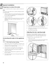
...a risk of the installation location must correspond to a drinking water line. Valuable raw materials can be located behind the appliance. Ventilation The refrigeration unit is easily accessible. Never cover the ventilation grille or place anything in the cold-water inflow....us by a competent fitter according to the local regulations of injuries and damage to the enclosed installation instructions. , WARNING: Do not install this appliance: ■ outdoors, ■ in an environment with dripping water, ■ in ! 4. A cold water connection is suitable as an installation...
...a risk of the installation location must correspond to a drinking water line. Valuable raw materials can be located behind the appliance. Ventilation The refrigeration unit is easily accessible. Never cover the ventilation grille or place anything in the cold-water inflow....us by a competent fitter according to the local regulations of injuries and damage to the enclosed installation instructions. , WARNING: Do not install this appliance: ■ outdoors, ■ in an environment with dripping water, ■ in ! 4. A cold water connection is suitable as an installation...