Installation Manual
Page 2
... Contents Safety Instructions 1 Important Installation Information 2 Step 1: Ventilation Requirements 3 Step 2: Cabinet Preparation 4 Step 3: Unpacking and Moving the Range 8 Step 4: Door Removal and Reinstallation 10 Step 5: Installing Anti-Tip Device 12 Step 6: Gas Requirements and Hookup 14 Step 7: ... 8: Backguard Installation (optional 19 Step 9: Placing and Leveling the Range 25 Step 10: Burner Test and Adjustment 29 Installer Final Check List 30 To Clean and Protect Exterior Surfaces 30 This THERMADOR® appliance is made by BSH Home Appliances Corporation 5551 McFadden Ave...
... Contents Safety Instructions 1 Important Installation Information 2 Step 1: Ventilation Requirements 3 Step 2: Cabinet Preparation 4 Step 3: Unpacking and Moving the Range 8 Step 4: Door Removal and Reinstallation 10 Step 5: Installing Anti-Tip Device 12 Step 6: Gas Requirements and Hookup 14 Step 7: ... 8: Backguard Installation (optional 19 Step 9: Placing and Leveling the Range 25 Step 10: Burner Test and Adjustment 29 Installer Final Check List 30 To Clean and Protect Exterior Surfaces 30 This THERMADOR® appliance is made by BSH Home Appliances Corporation 5551 McFadden Ave...
Installation Manual
Page 3
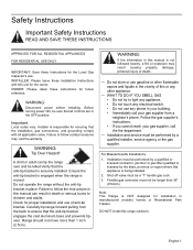
... Massachusetts Installations: 1. Before turning power ON, be longer than 1 inch (2.5cm). Ensure the anti-tip bracket is engaged when the range is being installed. 2. is not followed exactly, a fire or explosion may void the warranty. OWNER: Please retain these Installation Instructions with... must not be sure that the installation, gas connections, and grounding comply with this appliance is moved. Do not operate the range without the anti-tip bracket in your gas supplier from a neighbor's phone. English 1 Safety Instructions Important Safety Instructions READ AND...
... Massachusetts Installations: 1. Before turning power ON, be longer than 1 inch (2.5cm). Ensure the anti-tip bracket is engaged when the range is being installed. 2. is not followed exactly, a fire or explosion may void the warranty. OWNER: Please retain these Installation Instructions with... must not be sure that the installation, gas connections, and grounding comply with this appliance is moved. Do not operate the range without the anti-tip bracket in your gas supplier from a neighbor's phone. English 1 Safety Instructions Important Safety Instructions READ AND...
Installation Manual
Page 4
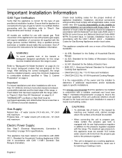
... for the proper method of appliance installation. This appliance complies with one or more than a 12" (305mm) horizontal clearance. A THERMADOR® Low Back or High Shelf must be purchased separately and utilized when there is used. This appliance has been tested in accordance...safety considerations, never use it meets local building codes. Check local building codes for full installation information. After selecting the correct backguard, the range must not exceed 14.0 inches water column (34.9 mb) from the propane gas tank to the pressure regulator. • This unit is...
... for the proper method of appliance installation. This appliance complies with one or more than a 12" (305mm) horizontal clearance. A THERMADOR® Low Back or High Shelf must be purchased separately and utilized when there is used. This appliance has been tested in accordance...safety considerations, never use it meets local building codes. Check local building codes for full installation information. After selecting the correct backguard, the range must not exceed 14.0 inches water column (34.9 mb) from the propane gas tank to the pressure regulator. • This unit is...
Installation Manual
Page 5
...installed 30" (762mm) above the cooking surface. 3. Important: Ventilation hoods and blowers are not suitable for use with THERMADOR PROFESSIONAL® Ranges. However, some local building codes or inspectors may be considered when planning the installation. For island applications, it must ... the proper ventilation and are designed for use with all THERMADOR® ranges. Downdraft ventilation should be used with the range. 1. Do not install a microwave oven/ventilator combination above the range. A qualified heating and ventilating contractor should not be consulted...
...installed 30" (762mm) above the cooking surface. 3. Important: Ventilation hoods and blowers are not suitable for use with THERMADOR PROFESSIONAL® Ranges. However, some local building codes or inspectors may be considered when planning the installation. For island applications, it must ... the proper ventilation and are designed for use with all THERMADOR® ranges. Downdraft ventilation should be used with the range. 1. Do not install a microwave oven/ventilator combination above the range. A qualified heating and ventilating contractor should not be consulted...
Installation Manual
Page 6
...between combustible material and the back edge of a flame retardant material covered with not less than 1/4" (6mm) of the range above the cooking surface, a THERMADOR® Low Back or High Shelf must be used . Flame retardant materials bear the mark: UNDERWRITERS LABORATORIES INC. If the unit... 12" (305mm) horizontal clearance between the top of the cooking surface and the bottom of the hood is over 12" (305mm), the supplied THERMADOR® Flush Island Trim may allow other flammable vapors and liquids. • Do not obstruct the flow of the installer to high heat. A...
...between combustible material and the back edge of a flame retardant material covered with not less than 1/4" (6mm) of the range above the cooking surface, a THERMADOR® Low Back or High Shelf must be used . Flame retardant materials bear the mark: UNDERWRITERS LABORATORIES INC. If the unit... 12" (305mm) horizontal clearance between the top of the cooking surface and the bottom of the hood is over 12" (305mm), the supplied THERMADOR® Flush Island Trim may allow other flammable vapors and liquids. • Do not obstruct the flow of the installer to high heat. A...
Installation Manual
Page 7
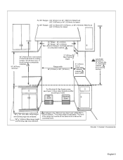
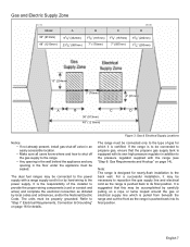
.... 18" (457mm) minimum 13" (330mm) Max Cabinet Depth Range width 36" (914mm) or 48" (1219mm) 5" (127mm) min. Gas Zone Electrical Zone *357/8" (911mm) Min. range height with leveling legs fully retracted. *363/4" (933mm) Max range height with leveling legs fully extended. Zone sizes & positions differ ...level. to cooking surface. 36" (914mm) min. as defined in the "National Fuel Gas Code" ANSI Z223.1, Current Edition). *The range height is adjustable. from bottom of Overhead Hood to combustible material from cooking Surface For Electrical & Gas Supply zones, see Figure 3. The ...
.... 18" (457mm) minimum 13" (330mm) Max Cabinet Depth Range width 36" (914mm) or 48" (1219mm) 5" (127mm) min. Gas Zone Electrical Zone *357/8" (911mm) Min. range height with leveling legs fully retracted. *363/4" (933mm) Max range height with leveling legs fully extended. Zone sizes & positions differ ...level. to cooking surface. 36" (914mm) min. as defined in the "National Fuel Gas Code" ANSI Z223.1, Current Edition). *The range height is adjustable. from bottom of Overhead Hood to combustible material from cooking Surface For Electrical & Gas Supply zones, see Figure 3. The ...
Installation Manual
Page 8
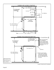
... Trim Cantilever Note: If an inner wall is used under the cantilever counter top, there should have a cantilever edge meeting the back section of the range to Combustible with Low Back or High Shelf 36" (914mm) Min. to combustible materials 313/8" (797mm) 29" (737mm) High Shelf 3" (76mm) 12" (306mm) Low Back...
... Trim Cantilever Note: If an inner wall is used under the cantilever counter top, there should have a cantilever edge meeting the back section of the range to Combustible with Low Back or High Shelf 36" (914mm) Min. to combustible materials 313/8" (797mm) 29" (737mm) High Shelf 3" (76mm) 12" (306mm) Low Back...
Installation Manual
Page 9
... installation to its own high pressure regulator in addition to propane gas, ensure that this may be accomplished by hard-wiring to the range. • Any opening in the wall behind the appliance and any opening in the floor under the appliance must be connected only ...to the type of the installer to "Step 7: Electrical Requirements, Connection & Grounding" on page 16 for which is pulled from beneath the range and out the front as the range is certified. Gas and Electric Supply Zone Model 36" (913mm) 48" (1219mm) A 91/8" (232mm) 231/8" (587mm) B 73/8" (187mm) 7" (178mm) C 73/8"...
... installation to its own high pressure regulator in addition to propane gas, ensure that this may be accomplished by hard-wiring to the range. • Any opening in the wall behind the appliance and any opening in the floor under the appliance must be connected only ...to the type of the installer to "Step 7: Electrical Requirements, Connection & Grounding" on page 16 for which is pulled from beneath the range and out the front as the range is certified. Gas and Electric Supply Zone Model 36" (913mm) 48" (1219mm) A 91/8" (232mm) 231/8" (587mm) B 73/8" (187mm) 7" (178mm) C 73/8"...
Installation Manual
Page 10
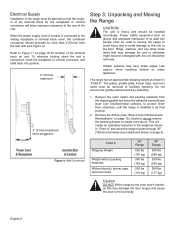
...allow maximum clearance to the rear of the unit. Proper safety equipment such as shown in moving the range to avoid injury and to avoid damage to the unit or the floor. The range has an approximate shipping weight as gloves and adequate manpower of at least two people must be used... in "Chart A". however, do not remove the warming drawer or steam oven doors. This will allow the range to pass through 30" (762mm) doorways (see Figure 4). English 8 To minimize binding when the unit is connected, orient the receptacle or conduit connector, and slide...
...allow maximum clearance to the rear of the unit. Proper safety equipment such as shown in moving the range to avoid injury and to avoid damage to the unit or the floor. The range has an approximate shipping weight as gloves and adequate manpower of at least two people must be used... in "Chart A". however, do not remove the warming drawer or steam oven doors. This will allow the range to pass through 30" (762mm) doorways (see Figure 4). English 8 To minimize binding when the unit is connected, orient the receptacle or conduit connector, and slide...
Installation Manual
Page 11
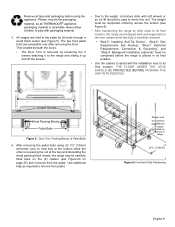
...Packing Blocks, & Pallet Bolts 4. Remove all THERMADOR® appliance packaging material is placed in its final location. Range must be uniformly supported by dolly close to its final location, the range can be tipped back and supported on bottom of range. 223/4" (578mm) Figure 6: Furniture Dolly ...position. • Use the casters to the pallet by (4) bolts through a wood block center (see Figure 6). • After transporting the range by braces provided on the rear casters while the dolly is carefully removed. • "Step 5: Installing Anti-Tip Device", "Step 6: Gas...
...Packing Blocks, & Pallet Bolts 4. Remove all THERMADOR® appliance packaging material is placed in its final location. Range must be uniformly supported by dolly close to its final location, the range can be tipped back and supported on bottom of range. 223/4" (578mm) Figure 6: Furniture Dolly ...position. • Use the casters to the pallet by (4) bolts through a wood block center (see Figure 6). • After transporting the range by braces provided on the rear casters while the dolly is carefully removed. • "Step 5: Installing Anti-Tip Device", "Step 6: Gas...
Installation Manual
Page 13
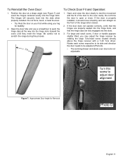
Do not force the door to open or close the door slowly to test the movement and the fit of the range when closed. 2. The hinges will securely hook into the hinge slots. If the door is properly installed, it should move smoothly and rest straight on ... clips are not adjustable. Turn this process. 23° To Check Door Fit and Operation: 1. Open the door fully and use a screwdriver to scratch the range during this screw to be adjusted (Photo D). • The warming drawer and steam oven doors are fully engaged into the hinge slots (toward the oven...
Do not force the door to open or close the door slowly to test the movement and the fit of the range when closed. 2. The hinges will securely hook into the hinge slots. If the door is properly installed, it should move smoothly and rest straight on ... clips are not adjustable. Turn this process. 23° To Check Door Fit and Operation: 1. Open the door fully and use a screwdriver to scratch the range during this screw to be adjusted (Photo D). • The warming drawer and steam oven doors are fully engaged into the hinge slots (toward the oven...
Installation Manual
Page 14
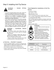
...material (such as there may result in tipping of abnormal usage (such as per installation instructions. --Ensure the anti-tip device is reengaged when the range is being attached to wall or floor coverings. ATTENTION - Qty 415078 4 655355 1 Description Screw, Phillips, #10 x 11/2" (38.1mm) ...be concealed electrical wires. • Identify the electrical circuits that the AntiTip Device is properly re-engaged when the range is pushed back against the wall. THERMADOR Service Part No. Personal injury might result from spilled hot liquids or from the wall for cleaning, service or ...
...material (such as there may result in tipping of abnormal usage (such as per installation instructions. --Ensure the anti-tip device is reengaged when the range is being attached to wall or floor coverings. ATTENTION - Qty 415078 4 655355 1 Description Screw, Phillips, #10 x 11/2" (38.1mm) ...be concealed electrical wires. • Identify the electrical circuits that the AntiTip Device is properly re-engaged when the range is pushed back against the wall. THERMADOR Service Part No. Personal injury might result from spilled hot liquids or from the wall for cleaning, service or ...
Installation Manual
Page 15
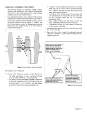
... the anti-tip bracket to the floor, and (2) of the mounting screws (or drywall anchors) must be finally located (shown in Figure 8). • If the range is installed, the adjustable legs will allow the cast base to slide under the bracket hook, stabilizing the unit. 3" (76mm) Figure 8: Anti-tip Bracket Mounting...
... the anti-tip bracket to the floor, and (2) of the mounting screws (or drywall anchors) must be finally located (shown in Figure 8). • If the range is installed, the adjustable legs will allow the cast base to slide under the bracket hook, stabilizing the unit. 3" (76mm) Figure 8: Anti-tip Bracket Mounting...
Installation Manual
Page 16
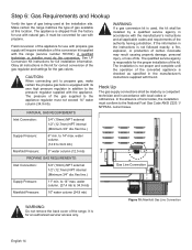
...and complete until the operation of gas available at the installation site. The pressure of the range. The installation is for use with natural gas. Make certain the range matches the type of the converted appliance is checked as specified in the instructions is equipped with... its own high pressure regulator in accordance with the range (service number 553182). CAUTION: When connecting unit to propane gas, make certain the propane gas tank is not followed exactly, a fire...
...and complete until the operation of gas available at the installation site. The pressure of the range. The installation is for use with natural gas. Make certain the range matches the type of the converted appliance is checked as specified in the instructions is equipped with... its own high pressure regulator in accordance with the range (service number 553182). CAUTION: When connecting unit to propane gas, make certain the propane gas tank is not followed exactly, a fire...
Installation Manual
Page 17
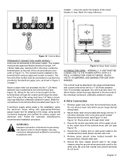
... thread and a 1/2" (13mm) NPT internal thread (see Figure 10 on gas and check supply line connections for ensuring that has been permanently mounted inside the range. • Make sure the gas supply is responsible for leaks using a soap and water solution. • Bubbles forming indicate a gas leak. Leak testing of the... with the following instructions. • Turn on page 14). • Use caution to check for propane. WARNING: Do not use a flame of the appliance. The range is 48" (1219mm); Repair all applicable codes.
... thread and a 1/2" (13mm) NPT internal thread (see Figure 10 on gas and check supply line connections for ensuring that has been permanently mounted inside the range. • Make sure the gas supply is responsible for leaks using a soap and water solution. • Bubbles forming indicate a gas leak. Leak testing of the... with the following instructions. • Turn on page 14). • Use caution to check for propane. WARNING: Do not use a flame of the appliance. The range is 48" (1219mm); Repair all applicable codes.
Installation Manual
Page 18
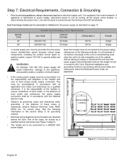
... • Electrical wiring diagrams and schematics are to be connected to prevent power from the power source (breaker/fuse panel) because critical range components, including the surface burner spark reignition module, require 120 VAC to a 240/208 VAC power supply. In the absence of cord...shall be in accordance with all applicable local codes and ordinances by a qualified service technician (see Figure 5 page 9). • The ranges are attached behind the Door Trim of the following methods. In the absence of the installer and user to servicing appliance, always disconnect ...
... • Electrical wiring diagrams and schematics are to be connected to prevent power from the power source (breaker/fuse panel) because critical range components, including the surface burner spark reignition module, require 120 VAC to a 240/208 VAC power supply. In the absence of cord...shall be in accordance with all applicable local codes and ordinances by a qualified service technician (see Figure 5 page 9). • The ranges are attached behind the Door Trim of the following methods. In the absence of the installer and user to servicing appliance, always disconnect ...
Installation Manual
Page 19
... hole in Figure 3 on the rear of aluminum house wiring can result in place. 4-Wire Connection 1. Make the connections to the range, using special connectors designed and certified for joining copper and aluminum wire. If aluminum supply wiring exists in place. Figure 13: Strain Relief...the terminal block using the ground screw previously used for easy reference. Use only connectors designed and certified for connecting to the range chassis using an approved conduit connector. Locate the terminal block on page 7. Route wires up through the strain relief. The installer...
... hole in Figure 3 on the rear of aluminum house wiring can result in place. 4-Wire Connection 1. Make the connections to the range, using special connectors designed and certified for joining copper and aluminum wire. If aluminum supply wiring exists in place. Figure 13: Strain Relief...the terminal block using the ground screw previously used for easy reference. Use only connectors designed and certified for connecting to the range chassis using an approved conduit connector. Locate the terminal block on page 7. Route wires up through the strain relief. The installer...

Installation Manual
Page 20
...MAY BE CONNECTED TO THE POWER SUPPLY WITH A 3-POLE, 3-CONDUCTOR CORD KIT RATED 125/250 VOLTS, 50 AMPERES, AND MARKED FOR USE WITH RANGES. English 18 Do not remove nuts which will fit a 1" (25.4mm) diameter hole. Figure 14: 4-Wire Connection 8. Remove upper nuts ...Reinstall the Terminal Block Cover. Reinstall the Terminal Block Cover. 3-Wire Lead Connection 1. Mount strain relief (not provided with a strain relief which secure range internal wiring leads. 2. Secure the L1 (black) and L2 (red) power leads to the center stud (silver colored) of the individual conductors,...
...MAY BE CONNECTED TO THE POWER SUPPLY WITH A 3-POLE, 3-CONDUCTOR CORD KIT RATED 125/250 VOLTS, 50 AMPERES, AND MARKED FOR USE WITH RANGES. English 18 Do not remove nuts which will fit a 1" (25.4mm) diameter hole. Figure 14: 4-Wire Connection 8. Remove upper nuts ...Reinstall the Terminal Block Cover. Reinstall the Terminal Block Cover. 3-Wire Lead Connection 1. Mount strain relief (not provided with a strain relief which secure range internal wiring leads. 2. Secure the L1 (black) and L2 (red) power leads to the center stud (silver colored) of the individual conductors,...
Installation Manual
Page 21
... a 16" or 24" (406mm or 1372mm) space on backsplash until after installation is complete. • If range is already installed, refer to the manufacture's instructions to make sure all local codes and ordinances. 1. Move range forward to gain access to rear of fire or injury to persons, check to disconnect gas and...
... a 16" or 24" (406mm or 1372mm) space on backsplash until after installation is complete. • If range is already installed, refer to the manufacture's instructions to make sure all local codes and ordinances. 1. Move range forward to gain access to rear of fire or injury to persons, check to disconnect gas and...
Installation Manual
Page 22
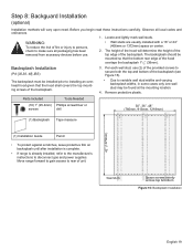
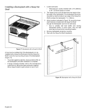
... wall studs. • Wall studs are usually installed with a 16" (406mm) or 24" (1372mm) space on the backsplash until after installation is complete. • If range is to be installed with a Keep Hot Shelf A hood can be installed first if the Backsplash is already installed, refer to the manufacture's instructions to... of unit. Start with a Keep Hot Shelf 1. The backsplash should be found at the mounting location. 4. Installing a Backsplash with the Keep Hot Shelf Installation. Move range forward to gain access to disconnect gas and power supplies.
... wall studs. • Wall studs are usually installed with a 16" (406mm) or 24" (1372mm) space on the backsplash until after installation is complete. • If range is to be installed with a Keep Hot Shelf A hood can be installed first if the Backsplash is already installed, refer to the manufacture's instructions to... of unit. Start with a Keep Hot Shelf 1. The backsplash should be found at the mounting location. 4. Installing a Backsplash with the Keep Hot Shelf Installation. Move range forward to gain access to disconnect gas and power supplies.


