

Instruction Manual
Page 2
... AV Spring on Fuel Tank 66 AV Spring on Handlebar 67 Stop Buffers 68 Buffers on Machines with Manual Fuel Pump 85 12.5 Carburetor 88 12.5.1 Leakage Test 89 RA_737_00_01_01 MS 231, MS 231 C, MS 251, MS 251 C q © ANDREAS STIHL AG & Co. Control Levers 71 10.1 Master Control Lever 71 10.1.1 Removing and Installing 71 10.2 Throttle...
... AV Spring on Fuel Tank 66 AV Spring on Handlebar 67 Stop Buffers 68 Buffers on Machines with Manual Fuel Pump 85 12.5 Carburetor 88 12.5.1 Leakage Test 89 RA_737_00_01_01 MS 231, MS 231 C, MS 251, MS 251 C q © ANDREAS STIHL AG & Co. Control Levers 71 10.1 Master Control Lever 71 10.1.1 Removing and Installing 71 10.2 Throttle...
Instruction Manual
Page 3
... Fuel Intake 101 12.11.1 Pickup Body 101 12.11.2 Fuel Hose 101 12.11.3 Fuel Hoses - Special Servicing Tools 110 14. Servicing Aids 112 2 MS 231, MS 231 C, MS 251, MS 251 C Manual Fuel Pump 105 12.11.4 Manual Fuel Pump 107 12.11.5 Tank Housing 108 13.
... Fuel Intake 101 12.11.1 Pickup Body 101 12.11.2 Fuel Hose 101 12.11.3 Fuel Hoses - Special Servicing Tools 110 14. Servicing Aids 112 2 MS 231, MS 231 C, MS 251, MS 251 C Manual Fuel Pump 105 12.11.4 Manual Fuel Pump 107 12.11.5 Tank Housing 108 13.

Instruction Manual
Page 4
...since they, depending on the machine may damage housings when the machine is held in the "STIHL Special Tools" manual. Refer to the latest edition of the relevant parts list to this service manual. Refer to the "Technical Information" bulletins for all the repair and servicing procedures specific to ..., secure the mounting plate (2) 5910 850 1650 to be taken that is issued. Introduction and Safety Precautions 2710RA320 TG 1.1 Introduction This service manual contains detailed descriptions of any replacement parts. MS 231, MS 231 C, MS 251, MS 251 C 3 To do this...
...since they, depending on the machine may damage housings when the machine is held in the "STIHL Special Tools" manual. Refer to the latest edition of the relevant parts list to this service manual. Refer to the "Technical Information" bulletins for all the repair and servicing procedures specific to ..., secure the mounting plate (2) 5910 850 1650 to be taken that is issued. Introduction and Safety Precautions 2710RA320 TG 1.1 Introduction This service manual contains detailed descriptions of any replacement parts. MS 231, MS 231 C, MS 251, MS 251 C 3 To do this...
Instruction Manual
Page 5
...STIHL press fluid, b 14. hose barb connectors Pull off or push on the fuel system and the engine. Do not smoke or bring any fire, flame or other source of engine damage due to the fuel hoses. replace as the safety precautions and warnings in damage to overheating. 4 MS 231, MS 231 C, MS 251, MS 251... bar before re-installing - Always use original STIHL replacement parts. Run the machine only with the connector, preferably by the STIHL part number, the { logo and the STIHL parts symbol K This symbol may result in the instruction manual. there is an extremely flammable fuel and can...
...STIHL press fluid, b 14. hose barb connectors Pull off or push on the fuel system and the engine. Do not smoke or bring any fire, flame or other source of engine damage due to the fuel hoses. replace as the safety precautions and warnings in damage to overheating. 4 MS 231, MS 231 C, MS 251, MS 251... bar before re-installing - Always use original STIHL replacement parts. Run the machine only with the connector, preferably by the STIHL part number, the { logo and the STIHL parts symbol K This symbol may result in the instruction manual. there is an extremely flammable fuel and can...
Instruction Manual
Page 6
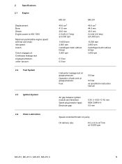
... mm 30.0 mm 2.0 kW (2.7 bhp) at 9,500 rpm 13,000 rpm 2,800 rpm Centrifugal clutch without linings 3,500 rpm 0.5 bar 0.5 bar MS 251 45.6 cm3 44.0 mm 30.0 mm 2.2 kW (3.0 bhp) at 9,500 rpm 13,000 rpm 2,800 rpm Centrifugal clutch without linings 3,500 rpm Carburetor...gauge pressure: Fuel: 0.8 bar 0.5 bar as specified in instruction manual Air gap between ignition module and fanwheel: Spark plug (resistor type): Electrode gap: 0.30 (+ 0.05/- 0.10) mm NGK CMR 6 H 0.5 mm Speed-controlled Ematic oil pump Oil delivery rate: 8.0 (+/3.0) cm3/min at 10,000 rpm MS 231, MS 231 C, MS 251, MS 251 C 5
... mm 30.0 mm 2.0 kW (2.7 bhp) at 9,500 rpm 13,000 rpm 2,800 rpm Centrifugal clutch without linings 3,500 rpm 0.5 bar 0.5 bar MS 251 45.6 cm3 44.0 mm 30.0 mm 2.2 kW (3.0 bhp) at 9,500 rpm 13,000 rpm 2,800 rpm Centrifugal clutch without linings 3,500 rpm Carburetor...gauge pressure: Fuel: 0.8 bar 0.5 bar as specified in instruction manual Air gap between ignition module and fanwheel: Spark plug (resistor type): Electrode gap: 0.30 (+ 0.05/- 0.10) mm NGK CMR 6 H 0.5 mm Speed-controlled Ematic oil pump Oil delivery rate: 8.0 (+/3.0) cm3/min at 10,000 rpm MS 231, MS 231 C, MS 251, MS 251 C 5
Instruction Manual
Page 20
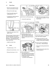
... (arrow) and the flat side of the clutch drum (1), check the remaining wall thickness. left-hand thread. - Remove and install the clutch drum, see instruction manual. - as shown in the reverse sequence. 2310RA005 TG 2310RA003 TG - Troubleshooting, b 4.2 - Remove the clutch drum, b 4.1 2310RA002 TG 1 2 Fit the cover washer (1) .... - Lubricate the needle cage and crankshaft stub, b 14 1 : Pull boot (1) off the spark plug. - 4. Clean the needle cage and crankshaft stub, b 14 - MS 231, MS 231 C, MS 251, MS 251 C 19 Inspect the clutch drum (1) for signs of wear.
... (arrow) and the flat side of the clutch drum (1), check the remaining wall thickness. left-hand thread. - Remove and install the clutch drum, see instruction manual. - as shown in the reverse sequence. 2310RA005 TG 2310RA003 TG - Troubleshooting, b 4.2 - Remove the clutch drum, b 4.1 2310RA002 TG 1 2 Fit the cover washer (1) .... - Lubricate the needle cage and crankshaft stub, b 14 1 : Pull boot (1) off the spark plug. - 4. Clean the needle cage and crankshaft stub, b 14 - MS 231, MS 231 C, MS 251, MS 251 C 19 Inspect the clutch drum (1) for signs of wear.
Instruction Manual
Page 21
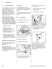
... chain brake released, open the throttle wide and activate the brake manually - If the chain brake does not operate properly, refer to one of the most important safety devices on inside diameter and/or parts of the machine. 20 MS 231, MS 231 C, MS 251, MS 251 C Troubleshooting, b 3.2 - Remove the brake band without overstretching it from the...
... chain brake released, open the throttle wide and activate the brake manually - If the chain brake does not operate properly, refer to one of the most important safety devices on inside diameter and/or parts of the machine. 20 MS 231, MS 231 C, MS 251, MS 251 C Troubleshooting, b 3.2 - Remove the brake band without overstretching it from the...
Instruction Manual
Page 29
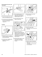
... (2) and tighten it home until the gap between the tank housing and engine housing to the right of the fuel hose (3) or, on versions with a manual fuel pump, to the recess (arrow) and then remove it from the retainer (4). : Fit the adjusting screw (1) and wind it down firmly. 1 : Pry the insert... return hose (2). : Push the brake cable (1), short hook (4) first, through the bore (arrow) in the engine housing. 1 2 : Push the insert (1) with the housing ribs. 28 MS 231, MS 231 C, MS 251, MS 251 C
... (2) and tighten it home until the gap between the tank housing and engine housing to the right of the fuel hose (3) or, on versions with a manual fuel pump, to the recess (arrow) and then remove it from the retainer (4). : Fit the adjusting screw (1) and wind it down firmly. 1 : Pry the insert... return hose (2). : Push the brake cable (1), short hook (4) first, through the bore (arrow) in the engine housing. 1 2 : Push the insert (1) with the housing ribs. 28 MS 231, MS 231 C, MS 251, MS 251 C
Instruction Manual
Page 33
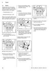
... sealing faces. 2 2310RA068 TG 2310RA070 TG 11 : Take out the screws (1). : Remove the muffler (2), check and replace if necessary. - see instruction manual. 6. Engine 2310RA071 TG 6.1 Muffler Always check and, if necessary, repair the fuel system, carburetor, air filter and ignition system before looking for faults on the cylinder. 32 MS 231, MS 231 C, MS 251, MS 251 C
... sealing faces. 2 2310RA068 TG 2310RA070 TG 11 : Take out the screws (1). : Remove the muffler (2), check and replace if necessary. - see instruction manual. 6. Engine 2310RA071 TG 6.1 Muffler Always check and, if necessary, repair the fuel system, carburetor, air filter and ignition system before looking for faults on the cylinder. 32 MS 231, MS 231 C, MS 251, MS 251 C
Instruction Manual
Page 72
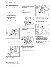
Control Levers 10.1 Master Control Lever - MS 231, MS 231 C, MS 251, MS 251 C 71 Remove the air filter, b 12.1 - Pull the filter base off the filter base's shaft (2). 1 : Check operation - Fit the contact spring, b 7.7.4 2310RA164 TG - short circuit wire's terminal sleeve must touch the contact spring (arrow) in the instruction manual. Check the filter base and replace...
Control Levers 10.1 Master Control Lever - MS 231, MS 231 C, MS 251, MS 251 C 71 Remove the air filter, b 12.1 - Pull the filter base off the filter base's shaft (2). 1 : Check operation - Fit the contact spring, b 7.7.4 2310RA164 TG - short circuit wire's terminal sleeve must touch the contact spring (arrow) in the instruction manual. Check the filter base and replace...
Instruction Manual
Page 78
...1 1 2310RA294 TG 2310RA297 TG 2310RA199 TG : Remove the fuel hose (1). Install the filter base, b 12.3 - All models - Models with manual fuel pump 1 2310RA200 TG 2 1 2310RA295 TG 2310RA298 TG : Carefully pull the carburetor (1) off the studs - Reassemble all other parts in the ... rod and replace if necessary Installing 2 : Push the carburetor (1) with fuel hose still attached to overstretch the fuel hose (2). - MS 231, MS 231 C, MS 251, MS 251 C 77 take care not to one side. 1 2 : Pass the throttle cable (1) between tank and engine housings and through the...
...1 1 2310RA294 TG 2310RA297 TG 2310RA199 TG : Remove the fuel hose (1). Install the filter base, b 12.3 - All models - Models with manual fuel pump 1 2310RA200 TG 2 1 2310RA295 TG 2310RA298 TG : Carefully pull the carburetor (1) off the studs - Reassemble all other parts in the ... rod and replace if necessary Installing 2 : Push the carburetor (1) with fuel hose still attached to overstretch the fuel hose (2). - MS 231, MS 231 C, MS 251, MS 251 C 77 take care not to one side. 1 2 : Pass the throttle cable (1) between tank and engine housings and through the...
Instruction Manual
Page 82
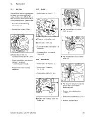
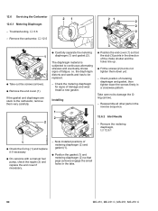
.... 2310RA198 TG 12. See also Troubleshooting, b 3.6, b 3.7 1 - see instruction manual. - Remove the choke rod, b 10.3.3 - Check the baffle and replace it if necessary : Rotate the air filter (1) counterclockwise and lift it away. - Reassemble in the reverse sequence. - Remove the contact spring, b 7.7.4 - MS 231, MS 231 C, MS 251, MS 251 C 81 Fuel System 12.1 Air Filter 12.2 Baffle Dirty...
.... 2310RA198 TG 12. See also Troubleshooting, b 3.6, b 3.7 1 - see instruction manual. - Remove the choke rod, b 10.3.3 - Check the baffle and replace it if necessary : Rotate the air filter (1) counterclockwise and lift it away. - Reassemble in the reverse sequence. - Remove the contact spring, b 7.7.4 - MS 231, MS 231 C, MS 251, MS 251 C 81 Fuel System 12.1 Air Filter 12.2 Baffle Dirty...
Instruction Manual
Page 86
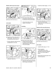
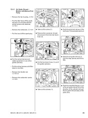
... the wiring harness and rubber grommet (1) out of the cylinder and pull the air guide shroud away at the same time. 2310RA338 TG MS 231, MS 231 C, MS 251, MS 251 C 85 Models with filter base to one side. - Pull the boot off the studs and put it to one side with the ... the manifold flange (1) out of the air guide shroud (2) in the direction of the guides (arrows). - 12.4.1 Air Guide Shroud - Put the wiring harness with Manual Fuel 2 Pump 1 - Remove the carburetor, b 12.5 - Pull the filter base off the spark plug. : Take out the screw (1). : Remove the connector (2) and ...
... the wiring harness and rubber grommet (1) out of the cylinder and pull the air guide shroud away at the same time. 2310RA338 TG MS 231, MS 231 C, MS 251, MS 251 C 85 Models with filter base to one side. - Pull the boot off the studs and put it to one side with the ... the manifold flange (1) out of the air guide shroud (2) in the direction of the guides (arrows). - 12.4.1 Air Guide Shroud - Put the wiring harness with Manual Fuel 2 Pump 1 - Remove the carburetor, b 12.5 - Pull the filter base off the spark plug. : Take out the screw (1). : Remove the connector (2) and ...
Instruction Manual
Page 89
... (3) must engage bore in place. - position short circuit wire under the ground wire. Install a new fuel hose, b 12.11.2 2310RA353 TG 88 MS 231, MS 231 C, MS 251, MS 251 C Install filter base with manual fuel pump - Open the fuel tank cap and drain the fuel tank. Check the carburetor and service or replace if necessary. - Make...
... (3) must engage bore in place. - position short circuit wire under the ground wire. Install a new fuel hose, b 12.11.2 2310RA353 TG 88 MS 231, MS 231 C, MS 251, MS 251 C Install filter base with manual fuel pump - Open the fuel tank cap and drain the fuel tank. Check the carburetor and service or replace if necessary. - Make...
Instruction Manual
Page 90
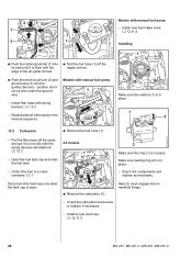
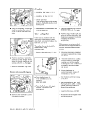
... - If this pressure remains constant, the carburetor is not sealing (foreign matter in the - Reassemble all other parts in the reverse sequence. MS 231, MS 231 C, MS 251, MS 251 C 89 Install the filter base, b 12.3 - Remove the carburetor, b 12.5 1. Set throttle trigger to the right and pump air... carburetor or fuel supply system, also check and clean or replace the tank vent, b 12.10 The carburetor can be tested for leaks with manual fuel pump 1 : Push the new fuel hose (1) onto the nipples (arrows). 2310RA356 TG 2310RA355 TG 2310RA354 TG 2310RA255 TG - 1 All ...
... - If this pressure remains constant, the carburetor is not sealing (foreign matter in the - Reassemble all other parts in the reverse sequence. MS 231, MS 231 C, MS 251, MS 251 C 89 Install the filter base, b 12.3 - Remove the carburetor, b 12.5 1. Set throttle trigger to the right and pump air... carburetor or fuel supply system, also check and clean or replace the tank vent, b 12.10 The carburetor can be tested for leaks with manual fuel pump 1 : Push the new fuel hose (1) onto the nipples (arrows). 2310RA356 TG 2310RA355 TG 2310RA354 TG 2310RA255 TG - 1 All ...
Instruction Manual
Page 91
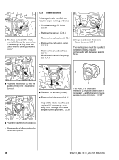
... TG 2310RA259 TG 1 : Check the O-ring (1) and replace it if necessary : On versions with a manual fuel pump, check the nipple (2) and replace the end cover if necessary. - Reassemble all other parts in the tabs. 90 MS 231, MS 231 C, MS 251, MS 251 C Note installed positions of metering diaphragm (2) and gasket (1). : Position the gasket (1) and metering diaphragm...
... TG 2310RA259 TG 1 : Check the O-ring (1) and replace it if necessary : On versions with a manual fuel pump, check the nipple (2) and replace the end cover if necessary. - Reassemble all other parts in the tabs. 90 MS 231, MS 231 C, MS 251, MS 251 C Note installed positions of metering diaphragm (2) and gasket (1). : Position the gasket (1) and metering diaphragm...
Instruction Manual
Page 99
...manifold and replace it snaps into the guide (arrow) until it if necessary - Reassemble all other parts in the reverse sequence. 98 MS 231, MS 231 C, MS 251, MS 251 C Remove the air guide shroud, b 12.4 Models with damaged sealing faces. 2310RA287 TG 2 1 2310RA359 TG 2310RA357 TG : Push... shroud, b 6.4 - Remove the carburetor, b 12.5 - even very minor damage can cause engine running problems, b 3.7 - Always replace components with manual fuel pump, b 12.4.1 : Inspect and clean the sealing faces (arrows), b 14 The sealing faces must be clear, clean if necessary - a dirty...
...manifold and replace it snaps into the guide (arrow) until it if necessary - Reassemble all other parts in the reverse sequence. 98 MS 231, MS 231 C, MS 251, MS 251 C Remove the air guide shroud, b 12.4 Models with damaged sealing faces. 2310RA287 TG 2 1 2310RA359 TG 2310RA357 TG : Push... shroud, b 6.4 - Remove the carburetor, b 12.5 - even very minor damage can cause engine running problems, b 3.7 - Always replace components with manual fuel pump, b 12.4.1 : Inspect and clean the sealing faces (arrows), b 14 The sealing faces must be clear, clean if necessary - a dirty...
Instruction Manual
Page 100
... (1). 2310RA362 TG 1 : Push the ring (1) to the left and connect the pump (2) 0000 850 1300 to the nipple (arrow) - Remove the carburetor, b 12.5 MS 231, MS 231 C, MS 251, MS 251 C 99 Models with manual fuel pump, b 12.4.1 - Clean the area around the tank vent. - Open the fuel tank cap and drain the fuel tank, b 1. - create a vacuum...
... (1). 2310RA362 TG 1 : Push the ring (1) to the left and connect the pump (2) 0000 850 1300 to the nipple (arrow) - Remove the carburetor, b 12.5 MS 231, MS 231 C, MS 251, MS 251 C 99 Models with manual fuel pump, b 12.4.1 - Clean the area around the tank vent. - Open the fuel tank cap and drain the fuel tank, b 1. - create a vacuum...
Instruction Manual
Page 102
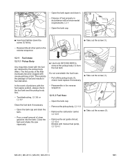
... in the reverse sequence. : Take out the screw (1). 1 2310RA371 TG 12.11 Fuel Intake 12.11.1 Pickup Body Any impurities mixed with manual fuel pump, b 12.4.1 2310RA374 TG MS 231, MS 231 C, MS 251, MS 251 C 101 Open the tank cap. Open the tank cap. 2310RA365 TG : Insert and tighten down the screw (1) firmly. - the fuel tank...
... in the reverse sequence. : Take out the screw (1). 1 2310RA371 TG 12.11 Fuel Intake 12.11.1 Pickup Body Any impurities mixed with manual fuel pump, b 12.4.1 2310RA374 TG MS 231, MS 231 C, MS 251, MS 251 C 101 Open the tank cap. Open the tank cap. 2310RA365 TG : Insert and tighten down the screw (1) firmly. - the fuel tank...
Instruction Manual
Page 105
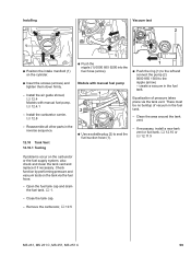
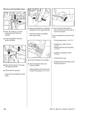
... tighten down the screw (2) firmly. : Ease the handlebar (1) sideways and place it down firmly. : Fit the AV spring (1) in the reverse sequence. 104 MS 231, MS 231 C, MS 251, MS 251 C Close the tank cap. - Do not overstretch the fuel suction hose. - Reassemble all other parts in position. : Insert and tighten down firmly. : Use... hose (1) from the fuel tank. Fit the pickup body, b 12.11.1 2 2 1 1 - Insert the screws and tighten them down the screw (2) firmly. - Machines with manual fuel pump, b 12.4.1 - Check position of fuel hose and correct if necessary, b 12.11.2 -
... tighten down the screw (2) firmly. : Ease the handlebar (1) sideways and place it down firmly. : Fit the AV spring (1) in the reverse sequence. 104 MS 231, MS 231 C, MS 251, MS 251 C Close the tank cap. - Do not overstretch the fuel suction hose. - Reassemble all other parts in position. : Insert and tighten down firmly. : Use... hose (1) from the fuel tank. Fit the pickup body, b 12.11.1 2 2 1 1 - Insert the screws and tighten them down the screw (2) firmly. - Machines with manual fuel pump, b 12.4.1 - Check position of fuel hose and correct if necessary, b 12.11.2 -


