

Instruction Manual
Page 4
... to third parties. MS 231, MS 231 C, MS 251, MS 251 C 3 Introduction and Safety Precautions 2710RA320 TG 1.1 Introduction This service manual contains detailed descriptions of all special servicing tools currently available from STIHL. The special tools mentioned in the illustration above the text In the illustrations: A Pointer a Direction of movement @ 4.2 =Reference to check the part numbers of the...
... to third parties. MS 231, MS 231 C, MS 251, MS 251 C 3 Introduction and Safety Precautions 2710RA320 TG 1.1 Introduction This service manual contains detailed descriptions of all special servicing tools currently available from STIHL. The special tools mentioned in the illustration above the text In the illustrations: A Pointer a Direction of movement @ 4.2 =Reference to check the part numbers of the...
Instruction Manual
Page 5
...manual. Run the machine only with STIHL press fluid and then push the new hoses on small parts. Gasoline is an extremely flammable fuel and can be performed outdoors only. replace as the safety precautions and warnings in damage to overheating. 4 MS 231, MS 231 C, MS 251, MS 251 C Fuel system - Coat the...oil in a clean container and dispose of it properly in accordance with a knife or similar tool. do not use original STIHL replacement parts. Other press fluids are heated for wear or damage before carrying out repairs or mounting the machine to the hose barbs, b 14....
...manual. Run the machine only with STIHL press fluid and then push the new hoses on small parts. Gasoline is an extremely flammable fuel and can be performed outdoors only. replace as the safety precautions and warnings in damage to overheating. 4 MS 231, MS 231 C, MS 251, MS 251 C Fuel system - Coat the...oil in a clean container and dispose of it properly in accordance with a knife or similar tool. do not use original STIHL replacement parts. Other press fluids are heated for wear or damage before carrying out repairs or mounting the machine to the hose barbs, b 14....
Instruction Manual
Page 19
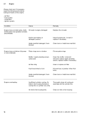
Fuel system - Clean bore or install new manifold. 3.7 Engine Always check and, if necessary, repair the following parts before looking for faults on fan housing 18 MS 231, MS 231 C, MS 251, MS 251 C Air filter - Ignition system Condition Cause Engine does not start easily, stalls Oil seals in fan housing dirty Clean air inlet on the engine...
Fuel system - Clean bore or install new manifold. 3.7 Engine Always check and, if necessary, repair the following parts before looking for faults on fan housing 18 MS 231, MS 231 C, MS 251, MS 251 C Air filter - Ignition system Condition Cause Engine does not start easily, stalls Oil seals in fan housing dirty Clean air inlet on the engine...
Instruction Manual
Page 20
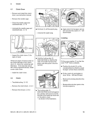
... flat side of the clutch drum (1), check the remaining wall thickness. as shown in the reverse sequence. 2310RA005 TG 2310RA003 TG - MS 231, MS 231 C, MS 251, MS 251 C 19 Clutch 4.1 Clutch Drum - Reassemble all other parts in the illustration. Clean the needle cage and crankshaft stub, b 14 - Unscrew the spark plug. 2310RA001 TG TOP 1 : Apply wrench...
... flat side of the clutch drum (1), check the remaining wall thickness. as shown in the reverse sequence. 2310RA005 TG 2310RA003 TG - MS 231, MS 231 C, MS 251, MS 251 C 19 Clutch 4.1 Clutch Drum - Reassemble all other parts in the illustration. Clean the needle cage and crankshaft stub, b 14 - Unscrew the spark plug. 2310RA001 TG TOP 1 : Apply wrench...
Instruction Manual
Page 21
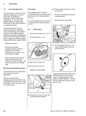
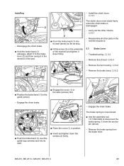
... particles of abrasion, etc.) and smoothing of the friction surfaces of the brake band and clutch drum impair the coefficient of the machine. 20 MS 231, MS 231 C, MS 251, MS 251 C arrows) and its seat (arrow). - to an abrupt stop . 2310RA007 TG 1 : Remove the screw (1) from the brake lever (2). 2310RA008 TG ...lever is in terms of outside diameter - Engage the chain brake. the chain must come areas on inside diameter and/or parts of the chain braking time, i.e. Disengage the chain brake 2 OP 1 : Turn the brake band (1) to troubleshooting, b 3.2.
... particles of abrasion, etc.) and smoothing of the friction surfaces of the brake band and clutch drum impair the coefficient of the machine. 20 MS 231, MS 231 C, MS 251, MS 251 C arrows) and its seat (arrow). - to an abrupt stop . 2310RA007 TG 1 : Remove the screw (1) from the brake lever (2). 2310RA008 TG ...lever is in terms of outside diameter - Engage the chain brake. the chain must come areas on inside diameter and/or parts of the chain braking time, i.e. Disengage the chain brake 2 OP 1 : Turn the brake band (1) to troubleshooting, b 3.2.
Instruction Manual
Page 22
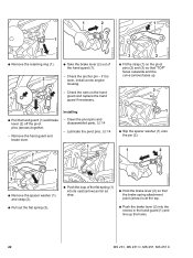
Remove the brake spring from the anchor pin (arrow). - Troubleshooting, b 3.2 - Engage the chain brake. Carry out the other parts in the reverse sequence. : Fit the screw (2) on the underside of the machine and tighten it in the direction of its seat.... the chain brake is now relaxed. : Use the assembly tool 1117 890 0900 to disconnect the brake spring (1) from the brake lever. 2310RA015 TG MS 231, MS 231 C, MS 251, MS 251 C 21 Engage the chain brake. 1 2 TOP 2 TOP 1 2310RA011 TG : Place the cover (1) in the slots (arrows) first. - Remove the shroud, b 6.4 - ...
Remove the brake spring from the anchor pin (arrow). - Troubleshooting, b 3.2 - Engage the chain brake. Carry out the other parts in the reverse sequence. : Fit the screw (2) on the underside of the machine and tighten it in the direction of its seat.... the chain brake is now relaxed. : Use the assembly tool 1117 890 0900 to disconnect the brake spring (1) from the brake lever. 2310RA015 TG MS 231, MS 231 C, MS 251, MS 251 C 21 Engage the chain brake. 1 2 TOP 2 TOP 1 2310RA011 TG : Place the cover (1) in the slots (arrows) first. - Remove the shroud, b 6.4 - ...
Instruction Manual
Page 23
... the pivot pins and disassembled parts, b 14 - if it is at the top. : Push the brake lever (2) into its seat (arrow) as far as stop. : Hold the brake lever (2) so that "TOP" faces outwards and the curve (arrow) faces up the holes. 2310RA023 TG 22 MS 231, MS 231 C, MS 251, MS 251 C Check the anchor pin...
... the pivot pins and disassembled parts, b 14 - if it is at the top. : Push the brake lever (2) into its seat (arrow) as far as stop. : Hold the brake lever (2) so that "TOP" faces outwards and the curve (arrow) faces up the holes. 2310RA023 TG 22 MS 231, MS 231 C, MS 251, MS 251 C Check the anchor pin...
Instruction Manual
Page 24
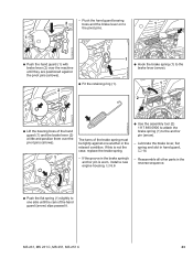
.... - Lubricate the brake lever, flat spring and slot in the relaxed condition. Reassemble all other parts in the reverse sequence. 2310RA026 TG : Push the flat spring (1) slightly to one another in hand guard, b 14 - MS 231, MS 231 C, MS 251, MS 251 C 23 If this is worn, install a new engine housing, b 6.6 2310RA028 TG : Use the assembly tool...
.... - Lubricate the brake lever, flat spring and slot in the relaxed condition. Reassemble all other parts in the reverse sequence. 2310RA026 TG : Push the flat spring (1) slightly to one another in hand guard, b 14 - MS 231, MS 231 C, MS 251, MS 251 C 23 If this is worn, install a new engine housing, b 6.6 2310RA028 TG : Use the assembly tool...
Instruction Manual
Page 25
... - Clean the pivot pins and disassembled parts, b 14 - Remove the shroud, b 6.4 - Remove the fan housing, b 8.2 - Remove the hand guard and brake lever. 2310RA033 TG 1 : Take the brake lever (2) out of the flat spring (1) into its seat (arrow) as far as stop. 2310RA020 TG 24 MS 231, MS 231 C, MS 251, MS 251 C if it is now relaxed...
... - Clean the pivot pins and disassembled parts, b 14 - Remove the shroud, b 6.4 - Remove the fan housing, b 8.2 - Remove the hand guard and brake lever. 2310RA033 TG 1 : Take the brake lever (2) out of the flat spring (1) into its seat (arrow) as far as stop. 2310RA020 TG 24 MS 231, MS 231 C, MS 251, MS 251 C if it is now relaxed...

Instruction Manual
Page 27
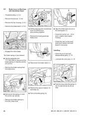
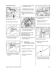
Adjust the brake cable, b 5.4.1 - Reassemble all other parts in the relaxed condition. Free travel is in the brake spring's anchor pin is worn, install a new engine housing, b 6.6 1 If problems occur on the coasting ... hold it in hand guard, b 14 - Release the lockout lever. - Free travel is released. : Carefully press the lockout lever (1) to the brake lever (arrow). 26 MS 231, MS 231 C, MS 251, MS 251 C Troubleshooting, b 3.2 - Checking condition and free travel . -
Adjust the brake cable, b 5.4.1 - Reassemble all other parts in the relaxed condition. Free travel is in the brake spring's anchor pin is worn, install a new engine housing, b 6.6 1 If problems occur on the coasting ... hold it in hand guard, b 14 - Release the lockout lever. - Free travel is released. : Carefully press the lockout lever (1) to the brake lever (arrow). 26 MS 231, MS 231 C, MS 251, MS 251 C Troubleshooting, b 3.2 - Checking condition and free travel . -
Instruction Manual
Page 28
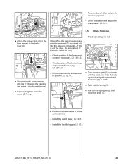
... engine housing (arrows) and the clutch drum must rotate freely. 2 1 - Disconnect the brake spring, b 5.4 1 - Check the brake cable (1) and retainer (2), replace if necessary MS 231, MS 231 C, MS 251, MS 251 C 27 Turn adjusting screw clockwise to stretch the hose. 2310RA044 TG 2310RA057 TG - Take care not to increase free travel on the adjusting screw... screw (1). 5.4.2 Brake cable Removing and Installing : Remove the retainer (2) with brake cable. - Remove the carburetor, b 12.5 - Remove the switch lever, b 10.3.1 2 - Reassemble all other parts in that position.
... engine housing (arrows) and the clutch drum must rotate freely. 2 1 - Disconnect the brake spring, b 5.4 1 - Check the brake cable (1) and retainer (2), replace if necessary MS 231, MS 231 C, MS 251, MS 251 C 27 Turn adjusting screw clockwise to stretch the hose. 2310RA044 TG 2310RA057 TG - Take care not to increase free travel on the adjusting screw... screw (1). 5.4.2 Brake cable Removing and Installing : Remove the retainer (2) with brake cable. - Remove the carburetor, b 12.5 - Remove the switch lever, b 10.3.1 2 - Reassemble all other parts in that position.
Instruction Manual
Page 30
... it in the reverse sequence. - Reassemble all other parts in position, b 12.11.2 1 : Turn the spur gear (2) clockwise until the tensioner slide (1) butts against the right-hand end and the screw (3) is not the case, the adjustment of the brake cable will vary. - Install the throttle trigger, b 10.3 MS 231, MS 231 C, MS 251, MS 251 C 29 1 2 1 2 -
... it in the reverse sequence. - Reassemble all other parts in position, b 12.11.2 1 : Turn the spur gear (2) clockwise until the tensioner slide (1) butts against the right-hand end and the screw (3) is not the case, the adjustment of the brake cable will vary. - Install the throttle trigger, b 10.3 MS 231, MS 231 C, MS 251, MS 251 C 29 1 2 1 2 -
Instruction Manual
Page 31
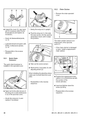
...adjusting wheel, make sure its teeth face the cover plate. - Clean all disassembled parts, b 14 - Check the wing nut (1) and replace if necessary 30 MS 231, MS 231 C, MS 251, MS 251 C Reassemble in the reverse sequence. - Swing the wing nut (1) upright. ...: Push the wing nut (1), thin side first (see arrow), into position. 1 2 1 The chain catcher (arrow) is installed in the reverse sequence. 1 : Position the replacement chain catcher (1) so that it lines up with STIHL...
...adjusting wheel, make sure its teeth face the cover plate. - Clean all disassembled parts, b 14 - Check the wing nut (1) and replace if necessary 30 MS 231, MS 231 C, MS 251, MS 251 C Reassemble in the reverse sequence. - Swing the wing nut (1) upright. ...: Push the wing nut (1), thin side first (see arrow), into position. 1 2 1 The chain catcher (arrow) is installed in the reverse sequence. 1 : Position the replacement chain catcher (1) so that it lines up with STIHL...
Instruction Manual
Page 32
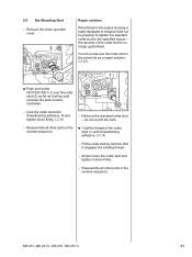
...damaged or stripped it down firmly, b 14 - do not re-drill the hole. - Reassemble all other parts in the engine housing is no longer guaranteed. Screw home the collar stud and tighten it will go and.... - the security of the collar stud (1) with threadlocking adhesive, fit and tighten down firmly. - Reassemble all other parts in the screw list as a repair solution, b 2.5. 1 2310RA046 TG 2310RA047 TG : Push stud puller 5910 893 .... Coat the collar stud with threadlocking adhesive, b 14 - 5.6 Bar Mounting Stud - MS 231, MS 231 C, MS 251, MS 251 C 31
...damaged or stripped it down firmly, b 14 - do not re-drill the hole. - Reassemble all other parts in the engine housing is no longer guaranteed. Screw home the collar stud and tighten it will go and.... - the security of the collar stud (1) with threadlocking adhesive, fit and tighten down firmly. - Reassemble all other parts in the screw list as a repair solution, b 2.5. 1 2310RA046 TG 2310RA047 TG : Push stud puller 5910 893 .... Coat the collar stud with threadlocking adhesive, b 14 - 5.6 Bar Mounting Stud - MS 231, MS 231 C, MS 251, MS 251 C 31
Instruction Manual
Page 34
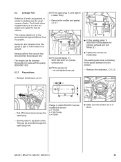
2310RA072 TG 2310RA074 TG 6.2 Leakage Test Defective oil seals and gaskets or cracks in place. 2310RA079 TG a 2710RA164 TG 2310RA073 TG MS 231, MS 231 C, MS 251, MS 251 C 33 Moreover, the transition from idle speed to part or full throttle is in castings are the usual causes of the prescribed idle speed difficult, if not impossible. The...
2310RA072 TG 2310RA074 TG 6.2 Leakage Test Defective oil seals and gaskets or cracks in place. 2310RA079 TG a 2710RA164 TG 2310RA073 TG MS 231, MS 231 C, MS 251, MS 251 C 33 Moreover, the transition from idle speed to part or full throttle is in castings are the usual causes of the prescribed idle speed difficult, if not impossible. The...
Instruction Manual
Page 35
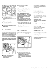
...left to vent the pump. - Remove the flange 1118 850 4200 from the crankshaft during the piston's induction stroke because there is airtight. 34 MS 231, MS 231 C, MS 251, MS 251 C Install the muffler, b 6.1 - 2 2 1 : Line up the flange (1) 1118 850 4200 and fit it can be carried ...out with pump 0000 850 1300 to detect this pressure remains constant for the vacuum test, b 6.2.2 3 2 - If the pressure drops, the leak must be located and the faulty part...
...left to vent the pump. - Remove the flange 1118 850 4200 from the crankshaft during the piston's induction stroke because there is airtight. 34 MS 231, MS 231 C, MS 251, MS 251 C Install the muffler, b 6.1 - 2 2 1 : Line up the flange (1) 1118 850 4200 and fit it can be carried ...out with pump 0000 850 1300 to detect this pressure remains constant for the vacuum test, b 6.2.2 3 2 - If the pressure drops, the leak must be located and the faulty part...
Instruction Manual
Page 36
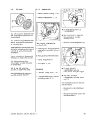
... jaws when removing the oil seals with its seat by tapping it with snap ring - jaws (No. 6) 0000 893 3711. MS 231, MS 231 C, MS 251, MS 251 C 35 Clamp the puller arms. - Reassemble all other parts in its open side facing the ball bearing. Lubricate sealing lips of new oil seal with grease, b 14 : Fit press...
... jaws when removing the oil seals with its seat by tapping it with snap ring - jaws (No. 6) 0000 893 3711. MS 231, MS 231 C, MS 251, MS 251 C 35 Clamp the puller arms. - Reassemble all other parts in its open side facing the ball bearing. Lubricate sealing lips of new oil seal with grease, b 14 : Fit press...
Instruction Manual
Page 37
Reassemble all other parts in its seat by 1 tapping it with a suitable tube or a punch. - Remove the shroud (1). 2310RA086 TG : Apply puller (1) 5910 890 4400. - Take care not to .... 1 2310RA084 TG - 6.3.2 Clutch side Installing - Remove the installing sleeve (1). 1 2 : Take out the screws (arrows). The seating face must be flat and free from burrs. 36 MS 231, MS 231 C, MS 251, MS 251 C Remove the clutch, b 4 - Clean the sealing face, b 14 -
Reassemble all other parts in its seat by 1 tapping it with a suitable tube or a punch. - Remove the shroud (1). 2310RA086 TG : Apply puller (1) 5910 890 4400. - Take care not to .... 1 2310RA084 TG - 6.3.2 Clutch side Installing - Remove the installing sleeve (1). 1 2 : Take out the screws (arrows). The seating face must be flat and free from burrs. 36 MS 231, MS 231 C, MS 251, MS 251 C Remove the clutch, b 4 - Clean the sealing face, b 14 -
Instruction Manual
Page 38
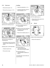
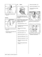
...12.11.5 2310RA089 TG 2310RA091 TG : Use a drift (2) to be in the reverse sequence. - If the sealing faces are damaged, replace the part concerned, b 3.7. : Remove the retaining ring (1). - Remove the clutch, b 4 - Remove the filter base, b 12.3 1 1 : Remove the... (1). - Remove the handlebar, b 9.4 1 - Remove the muffler, b 6.1 2 - Remove the air guide shroud, b 12.4 2310RA092 TG MS 231, MS 231 C, MS 251, MS 251 C 37 Remove the flywheel, b 7.6 - Remove the fan housing, b 8.2 - Reassemble all other parts in perfect condition. Remove the carburetor, b 12.5 -
...12.11.5 2310RA089 TG 2310RA091 TG : Use a drift (2) to be in the reverse sequence. - If the sealing faces are damaged, replace the part concerned, b 3.7. : Remove the retaining ring (1). - Remove the clutch, b 4 - Remove the filter base, b 12.3 1 1 : Remove the... (1). - Remove the handlebar, b 9.4 1 - Remove the muffler, b 6.1 2 - Remove the air guide shroud, b 12.4 2310RA092 TG MS 231, MS 231 C, MS 251, MS 251 C 37 Remove the flywheel, b 7.6 - Remove the fan housing, b 8.2 - Reassemble all other parts in perfect condition. Remove the carburetor, b 12.5 -
Instruction Manual
Page 39
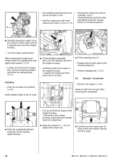
... upside down yet. : Carefully pry the engine pan (1) loose at the point shown (arrow) and lift it away. 38 MS 231, MS 231 C, MS 251, MS 251 C Carefully position the engine in the reverse sequence. - Reassemble all other parts in the engine housing - Perform leakage test, b 6.2 6.6 Cylinder / Crankshaft - do not tighten them down . Push the oil seals...
... upside down yet. : Carefully pry the engine pan (1) loose at the point shown (arrow) and lift it away. 38 MS 231, MS 231 C, MS 251, MS 251 C Carefully position the engine in the reverse sequence. - Reassemble all other parts in the engine housing - Perform leakage test, b 6.2 6.6 Cylinder / Crankshaft - do not tighten them down . Push the oil seals...


