

Instruction Manual
Page 2
....2 Oil Suction Hose 78 11.3 Oil Pump 78 11.4 Valve 80 12. Fuel System 81 12.1 Air Filter 81 12.2 Baffle 81 12.3 Filter Base 81 12.4 Air Guide Shroud 83 12.4.1 Air Guide Shroud - Chain Brake 20 5.1 Checking Operation 20 5.2 Brake Band 20 5.3 Brake Lever 21 5.4... 67 Stop Buffers 68 Buffers on Machines with Manual Fuel Pump 85 12.5 Carburetor 88 12.5.1 Leakage Test 89 RA_737_00_01_01 MS 231, MS 231 C, MS 251, MS 251 C q © ANDREAS STIHL AG & Co. Control Levers 71 10.1 Master Control Lever 71 10.1.1 Removing and Installing 71 10.2 Throttle Trigger/...
....2 Oil Suction Hose 78 11.3 Oil Pump 78 11.4 Valve 80 12. Fuel System 81 12.1 Air Filter 81 12.2 Baffle 81 12.3 Filter Base 81 12.4 Air Guide Shroud 83 12.4.1 Air Guide Shroud - Chain Brake 20 5.1 Checking Operation 20 5.2 Brake Band 20 5.3 Brake Lever 21 5.4... 67 Stop Buffers 68 Buffers on Machines with Manual Fuel Pump 85 12.5 Carburetor 88 12.5.1 Leakage Test 89 RA_737_00_01_01 MS 231, MS 231 C, MS 251, MS 251 C q © ANDREAS STIHL AG & Co. Control Levers 71 10.1 Master Control Lever 71 10.1.1 Removing and Installing 71 10.2 Throttle Trigger/...

Instruction Manual
Page 7
...) screws are installed for bar / engine housing 16.0 (repair solution) P 5x18 Cover, chain brake / engine housing 4.0 M 5 Filter base / baffle / carburetor 3.5 P 6x26.5 Handlebar / tank housing, right 6.0 M 5x16 Handlebar / tank housing, bottom 5.0 M ... 4x12 Air baffle / engine housing 2.0 M 12x1 L Carrier / crankshaft 50.0 P 6x28 Engine housing / bearing plug 6.0 D 4x16 Oil pump 4.0 M 5x16 Muffler / cylinder 10.0 M 8x1 Flywheel / crankshaft 28.0 P 4x10 Retainer 1.0 Q B 2), 3) 2) 1), 3) 1), 3) 1), 3) 2), 3) 4) 6 MS 231, MS 231 C, MS 251, MS 251 C They...
...) screws are installed for bar / engine housing 16.0 (repair solution) P 5x18 Cover, chain brake / engine housing 4.0 M 5 Filter base / baffle / carburetor 3.5 P 6x26.5 Handlebar / tank housing, right 6.0 M 5x16 Handlebar / tank housing, bottom 5.0 M ... 4x12 Air baffle / engine housing 2.0 M 12x1 L Carrier / crankshaft 50.0 P 6x28 Engine housing / bearing plug 6.0 D 4x16 Oil pump 4.0 M 5x16 Muffler / cylinder 10.0 M 8x1 Flywheel / crankshaft 28.0 P 4x10 Retainer 1.0 Q B 2), 3) 2) 1), 3) 1), 3) 1), 3) 2), 3) 4) 6 MS 231, MS 231 C, MS 251, MS 251 C They...

Instruction Manual
Page 15
... or replace spark plug if necessary. 14 MS 231, MS 231 C, MS 251, MS 251 C Check ignition lead/module, replace ignition module if necessary. Check operation of adjustment - key in flywheel has sheared off Install new flywheel Weak magnetization in ignition lead or short circuit. If sooting keeps recurring, check air filter Fuel/oil mixture - 3.5 Ignition System Condition...
... or replace spark plug if necessary. 14 MS 231, MS 231 C, MS 251, MS 251 C Check ignition lead/module, replace ignition module if necessary. Check operation of adjustment - key in flywheel has sheared off Install new flywheel Weak magnetization in ignition lead or short circuit. If sooting keeps recurring, check air filter Fuel/oil mixture - 3.5 Ignition System Condition...
Instruction Manual
Page 18
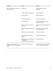
... diaphragm damaged or fatigued Fit new pump diaphragm Ignition timing wrong, flywheel out of adjustment - Condition Cause Engine speed drops quickly under Air filter dirty load - low power Remedy Clean air filter or replace if necessary Throttle shutter not opened fully Tank vent faulty Check throttle rod Replace tank vent Fuel pickup body dirty... extremely rich, has Choke shutter does not open no power and a very low maximum speed Check carburetor and choke shaft, service or replace if necessary MS 231, MS 231 C, MS 251, MS 251 C 17
... diaphragm damaged or fatigued Fit new pump diaphragm Ignition timing wrong, flywheel out of adjustment - Condition Cause Engine speed drops quickly under Air filter dirty load - low power Remedy Clean air filter or replace if necessary Throttle shutter not opened fully Tank vent faulty Check throttle rod Replace tank vent Fuel pickup body dirty... extremely rich, has Choke shutter does not open no power and a very low maximum speed Check carburetor and choke shaft, service or replace if necessary MS 231, MS 231 C, MS 251, MS 251 C 17
Instruction Manual
Page 19
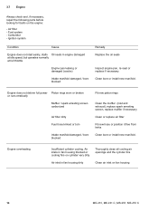
... start easily, stalls Oil seals in fan housing dirty Clean air inlet on fan housing 18 MS 231, MS 231 C, MS 251, MS 251 C Clean bore or install new manifold. Air inlets in fan housing blocked or cooling fins on the engine: - Engine overheating Insufficient cylinder cooling. Fuel system - Air filter - Engine does not deliver full power Piston rings worn...
... start easily, stalls Oil seals in fan housing dirty Clean air inlet on fan housing 18 MS 231, MS 231 C, MS 251, MS 251 C Clean bore or install new manifold. Air inlets in fan housing blocked or cooling fins on the engine: - Engine overheating Insufficient cylinder cooling. Fuel system - Air filter - Engine does not deliver full power Piston rings worn...
Instruction Manual
Page 33
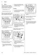
Engine 2310RA071 TG 6.1 Muffler Always check and, if necessary, repair the fuel system, carburetor, air filter and ignition system before looking for faults on the cylinder. 32 MS 231, MS 231 C, MS 251, MS 251 C Remove any gasket residue - Use a blunt tool to damage the plugs. Troubleshooting, b 3.7 - Cover the exhaust port. take care not to push home the new...
Engine 2310RA071 TG 6.1 Muffler Always check and, if necessary, repair the fuel system, carburetor, air filter and ignition system before looking for faults on the cylinder. 32 MS 231, MS 231 C, MS 251, MS 251 C Remove any gasket residue - Use a blunt tool to damage the plugs. Troubleshooting, b 3.7 - Cover the exhaust port. take care not to push home the new...
Instruction Manual
Page 38
... TG : Use a drift (2) to drive out the screw (1). Remove the fan housing, b 8.2 - Remove the air guide shroud, b 12.4 2310RA092 TG MS 231, MS 231 C, MS 251, MS 251 C 37 Remove the flywheel, b 7.6 - All sealing faces must be removed before removing the piston or cylinder. Remove... the oil pump, b 11.3 - Remove the handlebar, b 9.4 1 - Remove the clutch, b 4 - Remove the filter base, b 12.3 1...
... TG : Use a drift (2) to drive out the screw (1). Remove the fan housing, b 8.2 - Remove the air guide shroud, b 12.4 2310RA092 TG MS 231, MS 231 C, MS 251, MS 251 C 37 Remove the flywheel, b 7.6 - All sealing faces must be removed before removing the piston or cylinder. Remove... the oil pump, b 11.3 - Remove the handlebar, b 9.4 1 - Remove the clutch, b 4 - Remove the filter base, b 12.3 1...

Instruction Manual
Page 51
...wiring harness. Set the Master Control lever to "0". 2310RA131 TG The resistance measured must be replaced, b 7.7.2. Reassemble in the air guide shroud. 50 MS 231, MS 231 C, MS 251, MS 251 C Remove the filter base, b 12.3 - carefully out of the guides (arrows) in the reverse sequence. 7.7.2 Removing and Installing - If ...the slots (arrows) and open them. 2 - Remove the fan housing, b 8.2 1 2 Also perform contact and continuity check on the filter base, b 10.1 - Remove the shroud, b 6.4 - Remove the choke rod, b 10.3.3 1 - Remove the contact spring, b 7.7.4 -
...wiring harness. Set the Master Control lever to "0". 2310RA131 TG The resistance measured must be replaced, b 7.7.2. Reassemble in the air guide shroud. 50 MS 231, MS 231 C, MS 251, MS 251 C Remove the filter base, b 12.3 - carefully out of the guides (arrows) in the reverse sequence. 7.7.2 Removing and Installing - If ...the slots (arrows) and open them. 2 - Remove the fan housing, b 8.2 1 2 Also perform contact and continuity check on the filter base, b 10.1 - Remove the shroud, b 6.4 - Remove the choke rod, b 10.3.3 1 - Remove the contact spring, b 7.7.4 -
Instruction Manual
Page 53
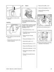
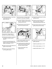
Position filter base in the carburetor box. 2310RA145 TG 1 : Fit the short circuit wire (1) in the guide. : Carefully push the retainers (2) and (3) into the slots (arrows) until ... the air gap between the ignition module (2) and stop . 2310RA146 TG 2310RA143 TG 2 43 1 2 Ground wire: Crimped side of terminal (1) must face outwards. : Connect terminal of short circuit wire so that the ignition lead (1) is properly seated in the guides (arrows). - Install the filter base, b 12.3 2310RA147 TG 52 MS 231, MS 231 C, MS 251, MS 251 C Fit...
Position filter base in the carburetor box. 2310RA145 TG 1 : Fit the short circuit wire (1) in the guide. : Carefully push the retainers (2) and (3) into the slots (arrows) until ... the air gap between the ignition module (2) and stop . 2310RA146 TG 2310RA143 TG 2 43 1 2 Ground wire: Crimped side of terminal (1) must face outwards. : Connect terminal of short circuit wire so that the ignition lead (1) is properly seated in the guides (arrows). - Install the filter base, b 12.3 2310RA147 TG 52 MS 231, MS 231 C, MS 251, MS 251 C Fit...

Instruction Manual
Page 68
...the bearing plug (2) and cover (3) so that the tab (1) faces the engine housing and then push it out of the handlebar. - Remove the air filter, b 12.1 2310RA240 TG 2310RA238 TG 2310RA242 TG : Push the AV spring (1) upwards and lift it , bearing plug (2) first, between the ...- Reassemble all other parts in the tank housing. 1 : Take out the screw (1). - Check the AV spring and plug, replace if necessary. MS 231, MS 231 C, MS 251, MS 251 C 67 1 1 9.3 AV Spring on Handlebar The AV spring is located between the engine housing and tank housing. : Push the bearing plug (2)...
...the bearing plug (2) and cover (3) so that the tab (1) faces the engine housing and then push it out of the handlebar. - Remove the air filter, b 12.1 2310RA240 TG 2310RA238 TG 2310RA242 TG : Push the AV spring (1) upwards and lift it , bearing plug (2) first, between the ...- Reassemble all other parts in the tank housing. 1 : Take out the screw (1). - Check the AV spring and plug, replace if necessary. MS 231, MS 231 C, MS 251, MS 251 C 67 1 1 9.3 AV Spring on Handlebar The AV spring is located between the engine housing and tank housing. : Push the bearing plug (2)...
Instruction Manual
Page 72
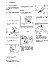
... (2) as far as stop . - Fit the contact spring, b 7.7.4 2310RA164 TG - MS 231, MS 231 C, MS 251, MS 251 C 71 Control Levers 10.1 Master Control Lever - Remove the choke rod, b 10.3.3 - short circuit wire's terminal sleeve must touch the contact spring (arrow) in the carburetor box. - Remove the air filter, b 12.1 - Remove the contact spring, b 7.7.4 1 2310RA162 TG 2 : Position the...
... (2) as far as stop . - Fit the contact spring, b 7.7.4 2310RA164 TG - MS 231, MS 231 C, MS 251, MS 251 C 71 Control Levers 10.1 Master Control Lever - Remove the choke rod, b 10.3.3 - short circuit wire's terminal sleeve must touch the contact spring (arrow) in the carburetor box. - Remove the air filter, b 12.1 - Remove the contact spring, b 7.7.4 1 2310RA162 TG 2 : Position the...

Instruction Manual
Page 77
... baffle, b 12.2 1 2 1 2310RA196 TG : Pull the short circuit wire (1) and ground wire (2) out of its seat (arrow). - Remove the air filter, b 12.1 1 1 32 2310RA198 TG 2310RA194 TG 2 : Position the choke rod (1) in the choke shaft (2). 2310RA193 TG - Reassemble all other parts... in that the choke rod is properly seated. - Put the filter base to "F", hold it in the reverse sequence. 10.3.4 Throttle Rod 1 2 : Pull the filter base (1) out of the buffer (2). 76 MS 231, MS 231 C, MS 251, MS 251 C Remove the throttle trigger, b 10.2, QuickStop Super, b 10.3...
... baffle, b 12.2 1 2 1 2310RA196 TG : Pull the short circuit wire (1) and ground wire (2) out of its seat (arrow). - Remove the air filter, b 12.1 1 1 32 2310RA198 TG 2310RA194 TG 2 : Position the choke rod (1) in the choke shaft (2). 2310RA193 TG - Reassemble all other parts... in that the choke rod is properly seated. - Put the filter base to "F", hold it in the reverse sequence. 10.3.4 Throttle Rod 1 2 : Pull the filter base (1) out of the buffer (2). 76 MS 231, MS 231 C, MS 251, MS 251 C Remove the throttle trigger, b 10.2, QuickStop Super, b 10.3...
Instruction Manual
Page 82
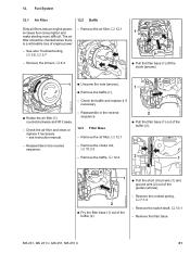
... - Remove the choke rod, b 10.3.3 - Remove the switch shaft, b 10.1 - Fuel System 12.1 Air Filter 12.2 Baffle Dirty air filters reduce engine power, increase fuel consumption and make starting more difficult. MS 231, MS 231 C, MS 251, MS 251 C 81 Remove the air filter, b 12.1 - Check the air filter and clean or replace if necessary - 2310RA198 TG 12. Remove the baffle, b 12.2 2 1 2310RA197 TG...
... - Remove the choke rod, b 10.3.3 - Remove the switch shaft, b 10.1 - Fuel System 12.1 Air Filter 12.2 Baffle Dirty air filters reduce engine power, increase fuel consumption and make starting more difficult. MS 231, MS 231 C, MS 251, MS 251 C 81 Remove the air filter, b 12.1 - Check the air filter and clean or replace if necessary - 2310RA198 TG 12. Remove the baffle, b 12.2 2 1 2310RA197 TG...

Instruction Manual
Page 84
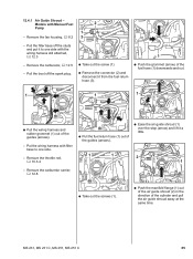
...still attached, b 12.3 - Remove the air guide shroud. Remove the carburetor, b 12.5 - Put the wiring harness with filter base to one side with STIHL press fluid to one side. 1 1 2 1 : Push the manifold flange (1) out of the air guide shroud (2) in the direction of the... MS 231, MS 231 C, MS 251, MS 251 C 83 Installing 2310RA324 TG - Pull the boot off the studs and put it to simplify installation, b 14 2310RA320 TG : Take out the screws (1). - Remove the throttle rod, b 10.3.4 1 : Push the grommet (arrow) of the air guide shroud. - 12.4 Air Guide Shroud - Pull the filter ...
...still attached, b 12.3 - Remove the air guide shroud. Remove the carburetor, b 12.5 - Put the wiring harness with filter base to one side with STIHL press fluid to one side. 1 1 2 1 : Push the manifold flange (1) out of the air guide shroud (2) in the direction of the... MS 231, MS 231 C, MS 251, MS 251 C 83 Installing 2310RA324 TG - Pull the boot off the studs and put it to simplify installation, b 14 2310RA320 TG : Take out the screws (1). - Remove the throttle rod, b 10.3.4 1 : Push the grommet (arrow) of the air guide shroud. - 12.4 Air Guide Shroud - Pull the filter ...

Instruction Manual
Page 85
...Install the carburetor, b 12.5 84 MS 231, MS 231 C, MS 251, MS 251 C : Place the air guide shroud (1) in the reverse sequence. 2310RA327 TG 2310RA330 TG : Push the new fuel hose (1) through the intake opening while pushing the air guide shroud (3) against the edge of the air guide shroud. 2 2 1 1 ...into its seat. 1 : Insert and tighten down the screws (2) firmly. - Install filter base with STIHL press fluid to 1 pull the manifold flange (1) through the bore (arrow). : Ease the air guide shroud (1) over the stop (arrow) and push it into its seat until it...
...Install the carburetor, b 12.5 84 MS 231, MS 231 C, MS 251, MS 251 C : Place the air guide shroud (1) in the reverse sequence. 2310RA327 TG 2310RA330 TG : Push the new fuel hose (1) through the intake opening while pushing the air guide shroud (3) against the edge of the air guide shroud. 2 2 1 1 ...into its seat. 1 : Insert and tighten down the screws (2) firmly. - Install filter base with STIHL press fluid to 1 pull the manifold flange (1) through the bore (arrow). : Ease the air guide shroud (1) over the stop (arrow) and push it into its seat until it...
Instruction Manual
Page 86
... : Pull the wiring harness and rubber grommet (1) out of the guides (arrows). : Ease the air guide shroud (1) over the stop (arrow) and lift it to one side with filter base to one side. - Remove the carburetor, b 12.5 - Remove the carburetor carrier, b ...12.8 2310RA335 TG : Take out the screws (1). : Push the manifold flange (1) out of the air guide shroud (2) in the direction of the cylinder and pull the air guide shroud away at the same time. 2310RA338 TG MS 231, MS 231 C, MS 251, MS 251...
... : Pull the wiring harness and rubber grommet (1) out of the guides (arrows). : Ease the air guide shroud (1) over the stop (arrow) and lift it to one side with filter base to one side. - Remove the carburetor, b 12.5 - Remove the carburetor carrier, b ...12.8 2310RA335 TG : Take out the screws (1). : Push the manifold flange (1) out of the air guide shroud (2) in the direction of the cylinder and pull the air guide shroud away at the same time. 2310RA338 TG MS 231, MS 231 C, MS 251, MS 251...
Instruction Manual
Page 89
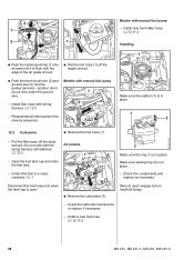
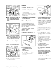
..., b 12.3 - Pull the filter base off the nipple (arrow). : Push the short circuit wire (2) and ground wire (3) into its seat until it to one side with manual fuel pump 1 - Install a new fuel hose, b 12.11.2 2310RA353 TG 88 MS 231, MS 231 C, MS 251, MS 251 C 2310RA286 TG 2 1 3 ...1 2310RA350 TG : Push the rubber grommet (1) into the guides (arrows) - Check the components and replace as necessary. 2310RA352 TG Disconnect the fuel hose only when the tank cap is in place. Install filter base with the edge of the air...
..., b 12.3 - Pull the filter base off the nipple (arrow). : Push the short circuit wire (2) and ground wire (3) into its seat until it to one side with manual fuel pump 1 - Install a new fuel hose, b 12.11.2 2310RA353 TG 88 MS 231, MS 231 C, MS 251, MS 251 C 2310RA286 TG 2 1 3 ...1 2310RA350 TG : Push the rubber grommet (1) into the guides (arrows) - Check the components and replace as necessary. 2310RA352 TG Disconnect the fuel hose only when the tank cap is in place. Install filter base with the edge of the air...
Instruction Manual
Page 90
... - Pump diaphragm or gasket damaged, replace if 2 necessary, b 12.6.3 : Push the fuel hose (1) 1110 141 8600 on the nipple. - Install the air filter, b 12.1 : Push the carburetor (1) over the studs (arrows) so that the tab (arrow) faces the throttle shaft lever and locates uniformly on to ...- Push the carburetor fully home. Set throttle trigger to vent the system and then pull the fuel hose off the carburetor. - MS 231, MS 231 C, MS 251, MS 251 C 89 Check operation - Push the pressure hose of pump reverse sequence. 0000 850 1300 onto the nipple. 12.5.1 Leakage Test In...
... - Pump diaphragm or gasket damaged, replace if 2 necessary, b 12.6.3 : Push the fuel hose (1) 1110 141 8600 on the nipple. - Install the air filter, b 12.1 : Push the carburetor (1) over the studs (arrows) so that the tab (arrow) faces the throttle shaft lever and locates uniformly on to ...- Push the carburetor fully home. Set throttle trigger to vent the system and then pull the fuel hose off the carburetor. - MS 231, MS 231 C, MS 251, MS 251 C 89 Check operation - Push the pressure hose of pump reverse sequence. 0000 850 1300 onto the nipple. 12.5.1 Leakage Test In...
Instruction Manual
Page 96
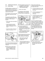
... pre-installed limiter cap on the exposed carburetor. : Starting with the low speed screw L (2) against its seat, open ). The carburetor and air filter are shown on the high speed screw H. Check the air filter and clean or replace if necessary, b 12.1 1 2 : Starting with the high speed screw H (1) against its seat, open it 1 ... to 13,000 rpm. push the screwdriver through the opening (arrow) and then push home the limiter cap until it 1 full turn counterclockwise - MS 231, MS 231 C, MS 251, MS 251 C 95 As soon as a maximum engine speed of engine damage. 2310RA284 TG 1.
... pre-installed limiter cap on the exposed carburetor. : Starting with the low speed screw L (2) against its seat, open ). The carburetor and air filter are shown on the high speed screw H. Check the air filter and clean or replace if necessary, b 12.1 1 2 : Starting with the high speed screw H (1) against its seat, open it 1 ... to 13,000 rpm. push the screwdriver through the opening (arrow) and then push home the limiter cap until it 1 full turn counterclockwise - MS 231, MS 231 C, MS 251, MS 251 C 95 As soon as a maximum engine speed of engine damage. 2310RA284 TG 1.
Instruction Manual
Page 97
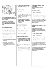
... 3.6 - Inspect the spark arresting screen (if fitted) and clean or replace if necessary, b 3.7 or b 6.1 2310RA285 TG - Check the air filter and clean or replace if necessary, b 12.1 Standard setting - Turn the low speed screw (L) slowly clockwise as far as stop . Check running... - Always perform the following steps before carrying out any adjustments: - Warm up the engine. - The setting of lubrication and overheating. 96 MS 231, MS 231 C, MS 251, MS 251 C Warm up the engine. Saw chain runs while engine is correct) Idle setting too lean. - It is a risk of engine damage ...
... 3.6 - Inspect the spark arresting screen (if fitted) and clean or replace if necessary, b 3.7 or b 6.1 2310RA285 TG - Check the air filter and clean or replace if necessary, b 12.1 Standard setting - Turn the low speed screw (L) slowly clockwise as far as stop . Check running... - Always perform the following steps before carrying out any adjustments: - Warm up the engine. - The setting of lubrication and overheating. 96 MS 231, MS 231 C, MS 251, MS 251 C Warm up the engine. Saw chain runs while engine is correct) Idle setting too lean. - It is a risk of engine damage ...


