
Instruction manual
Page 1
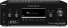
Record the serial number in the space provided below. Serial No. STR-DG810 ©2007 Sony Corporation 2-898-639-11(1) Multi Channel AV Receiver Operating Instructions Owner's Record The model and serial numbers are located on the rear of the unit. Refer to them whenever you call upon your Sony dealer regarding this product. Model No.
Record the serial number in the space provided below. Serial No. STR-DG810 ©2007 Sony Corporation 2-898-639-11(1) Multi Channel AV Receiver Operating Instructions Owner's Record The model and serial numbers are located on the rear of the unit. Refer to them whenever you call upon your Sony dealer regarding this product. Model No.

Instruction manual
Page 2
...of uninsulated "dangerous voltage" within the product's enclosure that may cause harmful interference to radio or television reception, which the receiver is connected. - For customers in cabinet. These limits are cautioned that provides guidelines for help. This equipment generates, uses,...the apparatus. If this system so that interference will not occur in accordance with general house waste; Reorient or relocate the receiving antenna. - Install this equipment does cause harmful interference to radio communications. And don't place lighted candles on the apparatus....
...of uninsulated "dangerous voltage" within the product's enclosure that may cause harmful interference to radio or television reception, which the receiver is connected. - For customers in cabinet. These limits are cautioned that provides guidelines for help. This equipment generates, uses,...the apparatus. If this system so that interference will not occur in accordance with general house waste; Reorient or relocate the receiving antenna. - Install this equipment does cause harmful interference to radio communications. And don't place lighted candles on the apparatus....

Instruction manual
Page 3
...under the US and foreign patents pending and other related technology owned by looking at the lower right corner of the front panel. This receiver incorporates High-Definition Multimedia Interface (HDMITM) technology. "Neural" and "Neural Audio" and "Neural Surround" are registered trademarks of DTS,...the illustration below). XM is a trademark of DTS, Inc. Sony Corporation hereby grants the user a nonexclusive, non-transferable, limited license right to the area code, are clearly indicated in the text, for model STR-DG810. About This Manual • The instructions in this manual are...
...under the US and foreign patents pending and other related technology owned by looking at the lower right corner of the front panel. This receiver incorporates High-Definition Multimedia Interface (HDMITM) technology. "Neural" and "Neural Audio" and "Neural Surround" are registered trademarks of DTS,...the illustration below). XM is a trademark of DTS, Inc. Sony Corporation hereby grants the user a nonexclusive, non-transferable, limited license right to the area code, are clearly indicated in the text, for model STR-DG810. About This Manual • The instructions in this manual are...

Instruction manual
Page 4
...2: Connecting speakers 16 3a: Connecting the audio components.........17 3b: Connecting the video components ........18 4: Connecting the antennas 26 5: Preparing the receiver and the remote .....27 6: Selecting the speaker system 28 7: Calibrating the appropriate settings automatically (AUTO CALIBRATION 29 8: Adjusting the speaker levels ...75 Naming inputs 76 Changing the display 77 Using the Sleep Timer 77 Recording using the receiver 78 Using the Remote Programming the remote 79 Additional Information Glossary 84 Precautions 86 Troubleshooting 87 Specifications 91 Index 93 ...
...2: Connecting speakers 16 3a: Connecting the audio components.........17 3b: Connecting the video components ........18 4: Connecting the antennas 26 5: Preparing the receiver and the remote .....27 6: Selecting the speaker system 28 7: Calibrating the appropriate settings automatically (AUTO CALIBRATION 29 8: Adjusting the speaker levels ...75 Naming inputs 76 Changing the display 77 Using the Sleep Timer 77 Recording using the receiver 78 Using the Remote Programming the remote 79 Additional Information Glossary 84 Precautions 86 Troubleshooting 87 Specifications 91 Index 93 ...

Instruction manual
Page 5
..., 63). MEMORY/ENTER Name Function E Display The current status of the selected component or a list of the front speakers. continued 5US F Remote sensor Receives signals from remote commander. Name Function A ?/1 (on/standby) Press to select information displayed on or off (page 27, 37, 38, 58, 91... MODE Press to select the input mode when the same components are connected to select "BASS LVL" or "TRE LVL", then turn the receiver on the display (page 67, 77). Adjusts the tonal quality (bass/treble level) of selectable items appears here (page 7). MOVIE MUSIC ...
..., 63). MEMORY/ENTER Name Function E Display The current status of the selected component or a list of the front speakers. continued 5US F Remote sensor Receives signals from remote commander. Name Function A ?/1 (on/standby) Press to select information displayed on or off (page 27, 37, 38, 58, 91... MODE Press to select the input mode when the same components are connected to select "BASS LVL" or "TRE LVL", then turn the receiver on the display (page 67, 77). Adjusts the tonal quality (bass/treble level) of selectable items appears here (page 7). MOVIE MUSIC ...

Instruction manual
Page 7
...Digital Surround EX signals are connected. D EX" lights up when the disc being played back contains an LFE (Low Frequency Effect) channel and the LFE channel signal is activated. PL IIx" lights up according to "NO" (page 42) and you have made digital connections and that ...reproduced. Lights up when the Pro Logic II Movie/Music/ Game decoder is set to output the center and surround channel signals. PL IIx ; continued 7US PL" lights up when the receiver applies Pro Logic processing to 2 channel signals in order to "ANALOG" (page 71). PL IIx F OPT Function "; ";
...Digital Surround EX signals are connected. D EX" lights up when the disc being played back contains an LFE (Low Frequency Effect) channel and the LFE channel signal is activated. PL IIx" lights up according to "NO" (page 42) and you have made digital connections and that ...reproduced. Lights up when the Pro Logic II Movie/Music/ Game decoder is set to output the center and surround channel signals. PL IIx ; continued 7US PL" lights up when the receiver applies Pro Logic processing to 2 channel signals in order to "ANALOG" (page 71). PL IIx F OPT Function "; ";

Instruction manual
Page 8
...SR S SB Function The letters (L, C, R, etc.) indicate the channels being input through the COAXIAL jack, or when INPUT MODE is a digital signal being played back. Lights up when using the receiver to show how the receiver downmixes the source sound (based on the speaker settings). For details ... Preset station indicators L D.RANGE M NEO:6 N COAX O HDMI Function "DTS" lights up when DTS signals are input. Lights up when the receiver recognizes a component connected via an HDMI IN jack (page 19). Lights up when DTS Neo:6 Cinema/Music decoder is decoding DTS 96 kHz/24 bit...
...SR S SB Function The letters (L, C, R, etc.) indicate the channels being input through the COAXIAL jack, or when INPUT MODE is a digital signal being played back. Lights up when using the receiver to show how the receiver downmixes the source sound (based on the speaker settings). For details ... Preset station indicators L D.RANGE M NEO:6 N COAX O HDMI Function "DTS" lights up when DTS signals are input. Lights up when the receiver recognizes a component connected via an HDMI IN jack (page 19). Lights up when DTS Neo:6 Cinema/Music decoder is decoding DTS 96 kHz/24 bit...

Instruction manual
Page 9
... section FM ANTENNA jack AM ANTENNA terminals XM jack Connects to the FM wire antenna supplied with this receiver) (page 63). Connects to the XM Connect-and-Play antenna (not supplied with this receiver (page 26). DMPORT Connects to a DVD player or a satellite tuner, etc. HDMI IN/ OUT jack* Connects to a DIGITAL... 19). Connects to a DVD player, etc. B DIGITAL INPUT/OUTPUT section OPTICAL IN jack COAXIAL IN jack Connects to the AM loop antenna supplied with this receiver (page 26). The COAXIAL jack provides a better quality of loud sound (page 22, 24).
... section FM ANTENNA jack AM ANTENNA terminals XM jack Connects to the FM wire antenna supplied with this receiver) (page 63). Connects to the XM Connect-and-Play antenna (not supplied with this receiver (page 26). DMPORT Connects to a DVD player or a satellite tuner, etc. HDMI IN/ OUT jack* Connects to a DIGITAL... 19). Connects to a DVD player, etc. B DIGITAL INPUT/OUTPUT section OPTICAL IN jack COAXIAL IN jack Connects to the AM loop antenna supplied with this receiver (page 26). The COAXIAL jack provides a better quality of loud sound (page 22, 24).

Instruction manual
Page 10
Remote commander You can use the supplied remote to operate the receiver and to control the Sony audio/video components that the remote is assigned to control non-Sony audio/video components. You can watch the selected input image when you connect the MONITOR OUT jack to sub woofer (page 16). RM-AAP016 e;... ql qk qj qh TV RM SET UP AV ?/1 ?/1 SYSTEM STANDBY VIDEO 1 VIDEO 2 VIDEO 3 DVD SAT TV SA-CD/CD TUNER AUX DMPORT RECEIVER 2CH...
Remote commander You can use the supplied remote to operate the receiver and to control the Sony audio/video components that the remote is assigned to control non-Sony audio/video components. You can watch the selected input image when you connect the MONITOR OUT jack to sub woofer (page 16). RM-AAP016 e;... ql qk qj qh TV RM SET UP AV ?/1 ?/1 SYSTEM STANDBY VIDEO 1 VIDEO 2 VIDEO 3 DVD SAT TV SA-CD/CD TUNER AUX DMPORT RECEIVER 2CH...

Instruction manual
Page 11
... or off. You can program the remote to activate the receiver operation (page 39). DMPORT DIGITAL MEDIA PORT adapter D RECEIVER E MOVIE, MUSIC F D.TUNING G AUTO CAL Press to control non-Sony components by changing the code. When you want to use. Press to activate the Auto...CD player TUNER Built-in tuner AUX Not assigned. Press to control Sony components as follows. continued 11US Getting Started Name A AV ?/1 (on/standby) B ?/1 (on/standby) Function Press to turn off the receiver and other components (SYSTEM STANDBY). If you press the input buttons (C)....
... or off. You can program the remote to activate the receiver operation (page 39). DMPORT DIGITAL MEDIA PORT adapter D RECEIVER E MOVIE, MUSIC F D.TUNING G AUTO CAL Press to control non-Sony components by changing the code. When you want to use. Press to activate the Auto...CD player TUNER Built-in tuner AUX Not assigned. Press to control Sony components as follows. continued 11US Getting Started Name A AV ?/1 (on/standby) B ?/1 (on/standby) Function Press to turn off the receiver and other components (SYSTEM STANDBY). If you press the input buttons (C)....

Instruction manual
Page 12
...- I ENTER Press to perform menu operations. Then, use V/v/B/b and to enter the value after selecting a channel, disc or track using the numeric buttons of the VCR, CD player, VCD player, LD player, DVD... or tape deck. Name Function H Numeric buttons (number 5a)) Press to preset stations. - select channel numbers of Sony TV, press TV (wl) and then press DISPLAY. To select information of the VCR, satellite tuner... COMBO. Press TV (wl) and then press the numeric buttons to display the menus of the receiver, VCR, DVD player, satellite tuner, Blu-ray disc recorder, PSX, DVD/ VHS COMBO or...
...- I ENTER Press to perform menu operations. Then, use V/v/B/b and to enter the value after selecting a channel, disc or track using the numeric buttons of the VCR, CD player, VCD player, LD player, DVD... or tape deck. Name Function H Numeric buttons (number 5a)) Press to preset stations. - select channel numbers of Sony TV, press TV (wl) and then press DISPLAY. To select information of the VCR, satellite tuner... COMBO. Press TV (wl) and then press the numeric buttons to display the menus of the receiver, VCR, DVD player, satellite tuner, Blu-ray disc recorder, PSX, DVD/ VHS COMBO or...

Instruction manual
Page 13
...DVD/HDD COMBO. to the previous menu. - Press also to enter the selection of Sony TV, press TV (wl), and then press RETURN/ EXIT O. To return to the previous menu of the receiver, VCR, satellite tuner, DVD player, Blu-ray disc recorder, PSX, DVD/VHS COMBO,...level. Name xb) Function Press to stop playback of the DVD player on the TV screen. Press to select preset TV channels. to scan a station. V V/v/B/b After pressing RECEIVER (D), press MENU (L) for receiver operation, then press V/v/B /b to enter the selection. After pressing DVD TOP MENU (P) or DVD MENU (P), press V/v/B/b...
...DVD/HDD COMBO. to the previous menu. - Press also to enter the selection of Sony TV, press TV (wl), and then press RETURN/ EXIT O. To return to the previous menu of the receiver, VCR, satellite tuner, DVD player, Blu-ray disc recorder, PSX, DVD/VHS COMBO,...level. Name xb) Function Press to stop playback of the DVD player on the TV screen. Press to select preset TV channels. to scan a station. V V/v/B/b After pressing RECEIVER (D), press MENU (L) for receiver operation, then press V/v/B /b to enter the selection. After pressing DVD TOP MENU (P) or DVD MENU (P), press V/v/B/b...

Instruction manual
Page 14
... satellite tuner. Name Function X -/-- To select the channel entry mode of the TV, press TV (wl) and then press -/--. >10 Press to serve as references when operating the receiver. wl TV Press to select the category mode for receiver operation. • Some functions explained in this section ... and V/v/B/b (V) buttons to set-up the button. RM SET UP Press to perform menu operations for Sony DIGITAL MEDIA PORT adapter operation. For details on the remote is also available for Sony TVs only. Press to clear a mistake when you press the incorrect numeric button of the VCR or ...
... satellite tuner. Name Function X -/-- To select the channel entry mode of the TV, press TV (wl) and then press -/--. >10 Press to serve as references when operating the receiver. wl TV Press to select the category mode for receiver operation. • Some functions explained in this section ... and V/v/B/b (V) buttons to set-up the button. RM SET UP Press to perform menu operations for Sony DIGITAL MEDIA PORT adapter operation. For details on the remote is also available for Sony TVs only. Press to clear a mistake when you press the incorrect numeric button of the VCR or ...

Instruction manual
Page 15
... speaker DSurround speaker (Left) ESurround speaker (Right) FSurround back speaker GSub woofer Tips • When you connect a 6.1 channel speaker system, place the surround back speaker behind the listening position. • Since the sub woofer does not emit highly ...Started 1: Installing speakers This receiver allows you to use a 6.1 channel system (6 speakers and one additional surround back speaker (6.1 channel) (see "Using the surround back decoding mode" on page 45). Enjoying a 5.1/6.1 channel system To fully enjoy theater-like multi channel surround sound requires five speakers ...
... speaker DSurround speaker (Left) ESurround speaker (Right) FSurround back speaker GSub woofer Tips • When you connect a 6.1 channel speaker system, place the surround back speaker behind the listening position. • Since the sub woofer does not emit highly ...Started 1: Installing speakers This receiver allows you to use a 6.1 channel system (6 speakers and one additional surround back speaker (6.1 channel) (see "Using the surround back decoding mode" on page 45). Enjoying a 5.1/6.1 channel system To fully enjoy theater-like multi channel surround sound requires five speakers ...

Instruction manual
Page 18
... connected" below for the pages which describe how to connect each component. Refer to the illustration that follows. INPUT jack COMPONENT HDMI VIDEO VIDEO Receiver HDMI OUT, MONITOR OUT jack COMPONENT HDMI VIDEO VIDEO ?/1 SPEAKERS (OFF/A/B/A+B) TONE MODE TONE TUNING MODE TUNING AUTO CAL MIC PHONES VIDEO 3... quality image Notes • Connect image display components such as a TV or a projector to the HDMI OUT or MONITOR OUT jack on the receiver. • Be sur to turn on your components. Before you begin, refer to "Component to be connected The image quality depends on , ...
... connected" below for the pages which describe how to connect each component. Refer to the illustration that follows. INPUT jack COMPONENT HDMI VIDEO VIDEO Receiver HDMI OUT, MONITOR OUT jack COMPONENT HDMI VIDEO VIDEO ?/1 SPEAKERS (OFF/A/B/A+B) TONE MODE TONE TUNING MODE TUNING AUTO CAL MIC PHONES VIDEO 3... quality image Notes • Connect image display components such as a TV or a projector to the HDMI OUT or MONITOR OUT jack on the receiver. • Be sur to turn on your components. Before you begin, refer to "Component to be connected The image quality depends on , ...

Instruction manual
Page 19
... Audio/video signals DVD player Audio/video signals HDMI feature A digital audio signals transmitted by HDMI can be output from the speakers connected to the receiver. Blu-ray disc player Audio/video signals TV, projector, etc. Audio/video signals A A A A SAT IN DVD IN VIDEO 2/BD IN OUT...SAT DVD VIDEO 1 WOOFER FRONT B R FRONT A SPEAKERS L SURROUND BACK R SURROUND CENTER A HDMI cable (not supplied) We recommend that you use a Sony HDMI cable. It is the abbreviated name for HighDefinition Multimedia Interface. This signal supports Dolby Digital, DTS and linear PCM.
... Audio/video signals DVD player Audio/video signals HDMI feature A digital audio signals transmitted by HDMI can be output from the speakers connected to the receiver. Blu-ray disc player Audio/video signals TV, projector, etc. Audio/video signals A A A A SAT IN DVD IN VIDEO 2/BD IN OUT...SAT DVD VIDEO 1 WOOFER FRONT B R FRONT A SPEAKERS L SURROUND BACK R SURROUND CENTER A HDMI cable (not supplied) We recommend that you use a Sony HDMI cable. It is the abbreviated name for HighDefinition Multimedia Interface. This signal supports Dolby Digital, DTS and linear PCM.

Instruction manual
Page 20
... copyright protection technology (HDCP), the image and/or the sound from the HDMI OUT jack may be distorted or may not be suppressed by Sony). • An audio signal input to the operating instructions of audio output signals from the playback component is switched. • When the ...and audio signals of the playback component to 720p or 1080i when you output 96 kHz multi-channel sound over a HDMI connection. • We do not recommend using an HDMI-DVI conversion cable. In this receiver. For details, see "Naming inputs" (page 76). When you connect an HDMI-DVI ...
... copyright protection technology (HDCP), the image and/or the sound from the HDMI OUT jack may be distorted or may not be suppressed by Sony). • An audio signal input to the operating instructions of audio output signals from the playback component is switched. • When the ...and audio signals of the playback component to 720p or 1080i when you output 96 kHz multi-channel sound over a HDMI connection. • We do not recommend using an HDMI-DVI conversion cable. In this receiver. For details, see "Naming inputs" (page 76). When you connect an HDMI-DVI ...

Instruction manual
Page 21
... (not supplied) 21US Connect audio and video cords according to the jacks of a playback component are being output to a TV via the receiver. If the power supply of this receiver can watch the selected input image when you connect the MONITOR OUT jack to a TV. • The sound of the TV is... output from a visual component connected to this receiver. It is transmitted. Tips • You can be displayed on a TV screen. Notes • Connect image display components such as a TV or a projector to the...
... (not supplied) 21US Connect audio and video cords according to the jacks of a playback component are being output to a TV via the receiver. If the power supply of this receiver can watch the selected input image when you connect the MONITOR OUT jack to a TV. • The sound of the TV is... output from a visual component connected to this receiver. It is transmitted. Tips • You can be displayed on a TV screen. Notes • Connect image display components such as a TV or a projector to the...

Instruction manual
Page 23
... can use the button to change the factory setting of the VIDEO 1 input button on the remote so that it can be displayed on the receiver's display. Connecting a DVD recorder Audio signals DVD recorder Video signals Getting Started D A AB B C SAT IN DVD IN VIDEO 2/BD IN OUT DIGITAL (ASSIGNABLE) OPTICAL ANTENNA...
... can use the button to change the factory setting of the VIDEO 1 input button on the remote so that it can be displayed on the receiver's display. Connecting a DVD recorder Audio signals DVD recorder Video signals Getting Started D A AB B C SAT IN DVD IN VIDEO 2/BD IN OUT DIGITAL (ASSIGNABLE) OPTICAL ANTENNA...

Instruction manual
Page 26
Notes • To prevent noise pickup, keep the AM loop antenna away from the receiver and other components. • Be sure to fully extend the FM wire antenna. • After connecting the FM wire antenna, keep it as horizontal as ... SUB SAT DVD VIDEO 1 WOOFER FRONT B R FRONT A SPEAKERS L SURROUND BACK R SURROUND CENTER * The shape of the connector varies depending on the area code of this receiver. 4: Connecting the antennas Connect the supplied AM loop antenna and FM wire antenna.
Notes • To prevent noise pickup, keep the AM loop antenna away from the receiver and other components. • Be sure to fully extend the FM wire antenna. • After connecting the FM wire antenna, keep it as horizontal as ... SUB SAT DVD VIDEO 1 WOOFER FRONT B R FRONT A SPEAKERS L SURROUND BACK R SURROUND CENTER * The shape of the connector varies depending on the area code of this receiver. 4: Connecting the antennas Connect the supplied AM loop antenna and FM wire antenna.


