
Limited Warranty (U.S. Only)
Page 1
4-557-173-02 General Stereo/Hifi Components/Tape Decks ® CD Players/Mini Disc Players/Audio Systems Hifi Audio LIMITED WARRANTY Sony Electronics Inc. ("Sony") warrants this Product is determined to be presented to any Sony authorized service facility. PARTS: In addition, Sony will repair or replace the Product, at its ...THIS PRODUCT IS LIMITED IN DURATION TO THE DURATION OF THIS WARRANTY. This warranty is valid only in the form of a bill of protection, to any part of sale, the limitation on how long an implied warranty lasts, so the above limitations or exclusions may not ...
4-557-173-02 General Stereo/Hifi Components/Tape Decks ® CD Players/Mini Disc Players/Audio Systems Hifi Audio LIMITED WARRANTY Sony Electronics Inc. ("Sony") warrants this Product is determined to be presented to any Sony authorized service facility. PARTS: In addition, Sony will repair or replace the Product, at its ...THIS PRODUCT IS LIMITED IN DURATION TO THE DURATION OF THIS WARRANTY. This warranty is valid only in the form of a bill of protection, to any part of sale, the limitation on how long an implied warranty lasts, so the above limitations or exclusions may not ...
Operating Instructions
Page 2
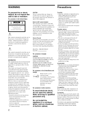
... the space provided below. Refer to them whenever you continuously use the receiver for help. 2 CAUTION You are not going to persons. Model No. STR-DE475/K402 Serial No. Refer servicing to provide reasonable protection against harmful interference in accordance with your nearest Sony dealer. Do not install the appliance in a confined space, such as...
... the space provided below. Refer to them whenever you continuously use the receiver for help. 2 CAUTION You are not going to persons. Model No. STR-DE475/K402 Serial No. Refer servicing to provide reasonable protection against harmful interference in accordance with your nearest Sony dealer. Do not install the appliance in a confined space, such as...

Operating Instructions
Page 42
...plugs and jacks are correct. Also, see page 16). 42 Should any of a short circuit. Turn off the receiver, eliminate the short-circuit problem and turn on page 19 to verify that the connecting cords are away from a ... 've selected the correct component on the receiver. , Press MUTING if MUTING appears on the display. , The protective device on the receiver has been activated because of the following difficulties while using the receiver, use this troubleshooting guide to either SMALL or.... Severe hum or noise is set or fluorescent light. , Move your nearest Sony dealer.
...plugs and jacks are correct. Also, see page 16). 42 Should any of a short circuit. Turn off the receiver, eliminate the short-circuit problem and turn on page 19 to verify that the connecting cords are away from a ... 've selected the correct component on the receiver. , Press MUTING if MUTING appears on the display. , The protective device on the receiver has been activated because of the following difficulties while using the receiver, use this troubleshooting guide to either SMALL or.... Severe hum or noise is set or fluorescent light. , Move your nearest Sony dealer.
Service Manual
Page 10
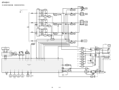
...R-CH is omitted due to same as L-CH. • Signal Path : FM L SL A C SW FL101 FLUORESCENT INDICATOR TUBE FL1 FL2 14 29 42 ... D721 OVER LOAD DETECT Q657,658 Q659 D606 D506 OVER LOAD DETECT Q507,509 IC401(2/2) 5 7 PROTECT SWITCH Q722,723,725 D731 D735 D734 D736 RELAY DRIVE Q791 RY791 RELAY DRIVE Q730 RY730 R-CH J791... AUDIO OUT 58 15 10 14 12 13 55 HP SW SIRCS 57 IC101 REMOTE 1 CONTROL 2 RECEIVER D109 VCC 23 VCC 84 RESET 77 HSTX 52 STOP 47 8 D101 B RESET D110 RESET Q100,...DRIVE Q901 RY901 E MODEL VOLTAGE SELECTOR S901 AC IN 10 10 STR-DE475 3-3. BLOCK DIAGRAM -
...R-CH is omitted due to same as L-CH. • Signal Path : FM L SL A C SW FL101 FLUORESCENT INDICATOR TUBE FL1 FL2 14 29 42 ... D721 OVER LOAD DETECT Q657,658 Q659 D606 D506 OVER LOAD DETECT Q507,509 IC401(2/2) 5 7 PROTECT SWITCH Q722,723,725 D731 D735 D734 D736 RELAY DRIVE Q791 RY791 RELAY DRIVE Q730 RY730 R-CH J791... AUDIO OUT 58 15 10 14 12 13 55 HP SW SIRCS 57 IC101 REMOTE 1 CONTROL 2 RECEIVER D109 VCC 23 VCC 84 RESET 77 HSTX 52 STOP 47 8 D101 B RESET D110 RESET Q100,...DRIVE Q901 RY901 E MODEL VOLTAGE SELECTOR S901 AC IN 10 10 STR-DE475 3-3. BLOCK DIAGRAM -


