
Limited Warranty (U.S. Only)
Page 1
4-557-173-02 General Stereo/Hifi Components/Tape Decks ® CD Players/Mini Disc Players/Audio Systems Hifi Audio LIMITED WARRANTY Sony Electronics Inc. ("Sony") warrants this Product is within 90 days of the date of two (2) year. has established telephone numbers for frequently ... negligence, commercial use, or modification of, or to any part of protection, to any accessories) against defects in the United States. SONY SHALL NOT BE LIABLE FOR ANY INCIDENTAL OR CONSEQUENTIAL DAMAGES FOR BREACH OF ANY EXPRESS OR IMPLIED WARRANTY ON THIS PRODUCT. This warranty is ...
4-557-173-02 General Stereo/Hifi Components/Tape Decks ® CD Players/Mini Disc Players/Audio Systems Hifi Audio LIMITED WARRANTY Sony Electronics Inc. ("Sony") warrants this Product is within 90 days of the date of two (2) year. has established telephone numbers for frequently ... negligence, commercial use, or modification of, or to any part of protection, to any accessories) against defects in the United States. SONY SHALL NOT BE LIABLE FOR ANY INCIDENTAL OR CONSEQUENTIAL DAMAGES FOR BREACH OF ANY EXPRESS OR IMPLIED WARRANTY ON THIS PRODUCT. This warranty is ...

Primary User Manual
Page 3
...demonstration will be cleared, see "Clearing the receiver's memory" on page 16. 3 For details on what will clear the receiver's memory. Table of Contents Parts Identification Main unit 4 Hooking Up the Components Required cords 5 Antenna hookups 6 Audio component hookups 7 Video component hookups 8 Digital ...25 Enjoying Surround Sound Selecting a sound field 26 Understanding the multi channel surround displays 30 Customizing sound fields 31 Receiving Broadcasts Direct tuning 36 Automatic tuning 36 Preset tuning 37 Other Operations Naming preset stations and program sources 38 ...
...demonstration will be cleared, see "Clearing the receiver's memory" on page 16. 3 For details on what will clear the receiver's memory. Table of Contents Parts Identification Main unit 4 Hooking Up the Components Required cords 5 Antenna hookups 6 Audio component hookups 7 Video component hookups 8 Digital ...25 Enjoying Surround Sound Selecting a sound field 26 Understanding the multi channel surround displays 30 Customizing sound fields 31 Receiving Broadcasts Direct tuning 36 Automatic tuning 36 Preset tuning 37 Other Operations Naming preset stations and program sources 38 ...
Primary User Manual
Page 5
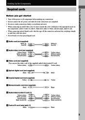
.... • Do not connect the AC power cord until they click into place. • Do not bend or tie the optical digital cord. white (left, audio) to white; Parts Identification/Hooking Up the Components Hooking Up the Components Required cords Before you get started • Turn off the connectors and insert...
.... • Do not connect the AC power cord until they click into place. • Do not bend or tie the optical digital cord. white (left, audio) to white; Parts Identification/Hooking Up the Components Hooking Up the Components Required cords Before you get started • Turn off the connectors and insert...
Primary User Manual
Page 6
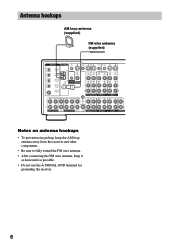
...IN VIDEO OUT VIDEO IN VIDEO S-VIDEO S-VIDEO OUT IN VIDEO VIDEO MD/DAT OPTICAL IN MD/DAT OPTICAL OUT U FM CONTROL 75Ω A1 MONITOR COAXIAL AUDIO IN L AUDIO IN AUDIO OUT AUDIO IN AUDIO OUT AUDIO IN L DVD/LD COAXIAL IN R TV/SAT DVD/LD VIDEO 2 R VIDEO 1 FRONT SURROUND CENTER FRONT SURROUND ... antenna hookups • To prevent noise pickup, keep the AM loop antenna away from the receiver and other components. • Be sure to fully extend the FM wire antenna. • After connecting the FM wire antenna, keep it as horizontal as possible. • Do not use the U SIGNAL...
...IN VIDEO OUT VIDEO IN VIDEO S-VIDEO S-VIDEO OUT IN VIDEO VIDEO MD/DAT OPTICAL IN MD/DAT OPTICAL OUT U FM CONTROL 75Ω A1 MONITOR COAXIAL AUDIO IN L AUDIO IN AUDIO OUT AUDIO IN AUDIO OUT AUDIO IN L DVD/LD COAXIAL IN R TV/SAT DVD/LD VIDEO 2 R VIDEO 1 FRONT SURROUND CENTER FRONT SURROUND ... antenna hookups • To prevent noise pickup, keep the AM loop antenna away from the receiver and other components. • Be sure to fully extend the FM wire antenna. • After connecting the FM wire antenna, keep it as horizontal as possible. • Do not use the U SIGNAL...

Primary User Manual
Page 7
Hooking Up the Components Audio component hookups Turntable A MD or DAT deck INPUT OUTPUT LINE LINE L R A A ç ç OUT IN ... VIDEO S-VIDEO S-VIDEO OUT IN VIDEO VIDEO MD/DAT OPTICAL IN MD/DAT OPTICAL OUT U FM CONTROL 75Ω A1 MONITOR COAXIAL AUDIO IN L AUDIO IN AUDIO OUT AUDIO IN AUDIO OUT AUDIO IN L DVD/LD COAXIAL IN R TV/SAT DVD/LD VIDEO 2 R VIDEO 1 FRONT ...OUTPUT LINE L R OUT A IN A INPUT OUTPUT LINE LINE L R CD or SACD player Tape deck Note on audio component hookups If your turntable has a ground wire, connect it to the U SIGNAL GND terminal. 7
Hooking Up the Components Audio component hookups Turntable A MD or DAT deck INPUT OUTPUT LINE LINE L R A A ç ç OUT IN ... VIDEO S-VIDEO S-VIDEO OUT IN VIDEO VIDEO MD/DAT OPTICAL IN MD/DAT OPTICAL OUT U FM CONTROL 75Ω A1 MONITOR COAXIAL AUDIO IN L AUDIO IN AUDIO OUT AUDIO IN AUDIO OUT AUDIO IN L DVD/LD COAXIAL IN R TV/SAT DVD/LD VIDEO 2 R VIDEO 1 FRONT ...OUTPUT LINE L R OUT A IN A INPUT OUTPUT LINE LINE L R CD or SACD player Tape deck Note on audio component hookups If your turntable has a ground wire, connect it to the U SIGNAL GND terminal. 7
Primary User Manual
Page 8
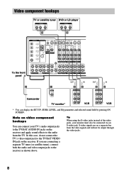
...by pressing ON SCREEN. If you are on the receiver. Tip When using the S-video jacks instead of the video jacks, your TV's audio output jacks to the TV/SAT AUDIO IN jacks on the receiver and apply sound effects to the audio from the video signals and will not be connected... IN VIDEO OUT VIDEO IN VIDEO S-VIDEO S-VIDEO OUT IN VIDEO VIDEO MD/DAT OPTICAL IN MD/DAT OPTICAL OUT U FM CONTROL 75Ω A1 MONITOR COAXIAL AUDIO IN L AUDIO IN AUDIO OUT AUDIO IN AUDIO OUT AUDIO IN L DVD/LD COAXIAL IN R TV/SAT DVD/LD VIDEO 2 R VIDEO 1 FRONT SURROUND CENTER FRONT SURROUND CENTER IN...
...by pressing ON SCREEN. If you are on the receiver. Tip When using the S-video jacks instead of the video jacks, your TV's audio output jacks to the TV/SAT AUDIO IN jacks on the receiver and apply sound effects to the audio from the video signals and will not be connected... IN VIDEO OUT VIDEO IN VIDEO S-VIDEO S-VIDEO OUT IN VIDEO VIDEO MD/DAT OPTICAL IN MD/DAT OPTICAL OUT U FM CONTROL 75Ω A1 MONITOR COAXIAL AUDIO IN L AUDIO IN AUDIO OUT AUDIO IN AUDIO OUT AUDIO IN L DVD/LD COAXIAL IN R TV/SAT DVD/LD VIDEO 2 R VIDEO 1 FRONT SURROUND CENTER FRONT SURROUND CENTER IN...
Primary User Manual
Page 9
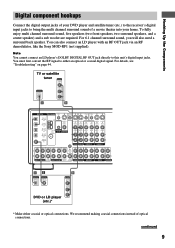
...player with an RF OUT jack via an RF demodulator, like the Sony MOD-RF1 (not supplied). For details, see "Troubleshooting" on page 44. TV or ...VIDEO MD/DAT OPTICAL IN MD/DAT OPTICAL OUT DVD/LD COAXIAL IN U FM CONTROL 75Ω A1 MONITOR COAXIAL AUDIO IN L AUDIO IN AUDIO OUT AUDIO IN AUDIO OUT AUDIO IN L R TV/SAT DVD/LD VIDEO 2 R VIDEO 1 FRONT ... connections instead of a movie theater into your DVD player and satellite tuner (etc.) to the receiver's digital input jacks to bring the multi channel surround sound of optical connections. You must first convert...
...player with an RF OUT jack via an RF demodulator, like the Sony MOD-RF1 (not supplied). For details, see "Troubleshooting" on page 44. TV or ...VIDEO MD/DAT OPTICAL IN MD/DAT OPTICAL OUT DVD/LD COAXIAL IN U FM CONTROL 75Ω A1 MONITOR COAXIAL AUDIO IN L AUDIO IN AUDIO OUT AUDIO IN AUDIO OUT AUDIO IN L R TV/SAT DVD/LD VIDEO 2 R VIDEO 1 FRONT ... connections instead of a movie theater into your DVD player and satellite tuner (etc.) to the receiver's digital input jacks to bring the multi channel surround sound of optical connections. You must first convert...
Primary User Manual
Page 10
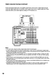
...VIDEO OUT VIDEO IN VIDEO S-VIDEO S-VIDEO OUT IN VIDEO VIDEO MD/DAT OPTICAL IN MD/DAT OPTICAL OUT U FM CONTROL 75Ω A1 MONITOR COAXIAL AUDIO IN L AUDIO IN AUDIO OUT AUDIO IN AUDIO OUT AUDIO IN L DVD/LD COAXIAL IN R TV/SAT DVD/LD VIDEO 2 R VIDEO 1 FRONT SURROUND CENTER FRONT ...may result in intermittent sound. 10 Digital component hookups (continued) Connect the digital output jacks of your MD or DAT deck to the receiver's digital input jack and connect the digital input jacks of digital multi channel surround signals. • To make analog and digital connections...
...VIDEO OUT VIDEO IN VIDEO S-VIDEO S-VIDEO OUT IN VIDEO VIDEO MD/DAT OPTICAL IN MD/DAT OPTICAL OUT U FM CONTROL 75Ω A1 MONITOR COAXIAL AUDIO IN L AUDIO IN AUDIO OUT AUDIO IN AUDIO OUT AUDIO IN L DVD/LD COAXIAL IN R TV/SAT DVD/LD VIDEO 2 R VIDEO 1 FRONT SURROUND CENTER FRONT ...may result in intermittent sound. 10 Digital component hookups (continued) Connect the digital output jacks of your MD or DAT deck to the receiver's digital input jack and connect the digital input jacks of digital multi channel surround signals. • To make analog and digital connections...
Primary User Manual
Page 11
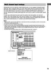
...VIDEO OUT VIDEO IN VIDEO S-VIDEO S-VIDEO OUT IN VIDEO VIDEO MD/DAT OPTICAL IN MD/DAT OPTICAL OUT U FM CONTROL 75Ω A1 MONITOR COAXIAL AUDIO IN L AUDIO IN AUDIO OUT AUDIO IN AUDIO OUT AUDIO IN L DVD/LD COAXIAL IN R TV/SAT DVD/LD VIDEO 2 R VIDEO 1 FRONT SURROUND CENTER FRONT ... two surround speakers, and a center speaker) and a sub woofer are required. Hooking Up the Components Multi channel input hookups Although this receiver incorporates a multi channel decoder, it is directly output from the surround back right speaker and the signal input at the MULTI CH IN...
...VIDEO OUT VIDEO IN VIDEO S-VIDEO S-VIDEO OUT IN VIDEO VIDEO MD/DAT OPTICAL IN MD/DAT OPTICAL OUT U FM CONTROL 75Ω A1 MONITOR COAXIAL AUDIO IN L AUDIO IN AUDIO OUT AUDIO IN AUDIO OUT AUDIO IN L DVD/LD COAXIAL IN R TV/SAT DVD/LD VIDEO 2 R VIDEO 1 FRONT SURROUND CENTER FRONT ... two surround speakers, and a center speaker) and a sub woofer are required. Hooking Up the Components Multi channel input hookups Although this receiver incorporates a multi channel decoder, it is directly output from the surround back right speaker and the signal input at the MULTI CH IN...
Primary User Manual
Page 12
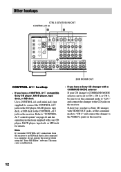
...a malfunction. • If you make CONTROL A1 connections from the receiver to an MD deck that is also connected to a computer, do not operate the receiver while using the "Sony MD Editor" software. Note If you have a Sony CD changer with a COMMAND MODE selector If your CD player, SACD... VIDEO OUT VIDEO IN VIDEO S-VIDEO S-VIDEO OUT IN VIDEO VIDEO MD/DAT OPTICAL IN MD/DAT OPTICAL OUT U FM CONTROL 75Ω A1 MONITOR COAXIAL AUDIO IN L AUDIO IN AUDIO OUT AUDIO IN AUDIO OUT AUDIO IN L DVD/LD COAXIAL IN R TV/SAT DVD/LD VIDEO 2 R VIDEO 1 FRONT SURROUND CENTER FRONT SURROUND...
...a malfunction. • If you make CONTROL A1 connections from the receiver to an MD deck that is also connected to a computer, do not operate the receiver while using the "Sony MD Editor" software. Note If you have a Sony CD changer with a COMMAND MODE selector If your CD player, SACD... VIDEO OUT VIDEO IN VIDEO S-VIDEO S-VIDEO OUT IN VIDEO VIDEO MD/DAT OPTICAL IN MD/DAT OPTICAL OUT U FM CONTROL 75Ω A1 MONITOR COAXIAL AUDIO IN L AUDIO IN AUDIO OUT AUDIO IN AUDIO OUT AUDIO IN L DVD/LD COAXIAL IN R TV/SAT DVD/LD VIDEO 2 R VIDEO 1 FRONT SURROUND CENTER FRONT SURROUND...
Primary User Manual
Page 13
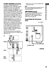
... VCR or DVD. TV S-LINK OUT IN VIDEO IN AUDIO OUT Receiver H G* CTRL S IN CTRL S STATUS IN CTRL S OUT CTRL S OUT S-VIDEO OUT VIDEO S-VIDEO S-VIDEO IN IN VIDEO VIDEO S-VIDEO S-VIDEO OUT IN VIDEO VIDEO MONITOR AUDIO AUDIO IN IN AUDIO AUDIO OUT IN VCR 1 TV/SAT DVD/LD VIDEO 1 ... TV. Hooking Up the Components S-LINK CONTROL S hookup If you have a S-LINK CONTROL Scompatible Sony TV, satellite tuner, monitor, DVD player or VCR, use the 2ND ROOM OUT jacks to output the audio signals of the selected component to a stereo amplifier located in another room (see page 25).
... VCR or DVD. TV S-LINK OUT IN VIDEO IN AUDIO OUT Receiver H G* CTRL S IN CTRL S STATUS IN CTRL S OUT CTRL S OUT S-VIDEO OUT VIDEO S-VIDEO S-VIDEO IN IN VIDEO VIDEO S-VIDEO S-VIDEO OUT IN VIDEO VIDEO MONITOR AUDIO AUDIO IN IN AUDIO AUDIO OUT IN VCR 1 TV/SAT DVD/LD VIDEO 1 ... TV. Hooking Up the Components S-LINK CONTROL S hookup If you have a S-LINK CONTROL Scompatible Sony TV, satellite tuner, monitor, DVD player or VCR, use the 2ND ROOM OUT jacks to output the audio signals of the selected component to a stereo amplifier located in another room (see page 25).
Primary User Manual
Page 14
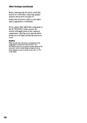
...turn the whole system on or off . Connect the AC power cord(s) of your audio/ video components to the receiver's AC OUTLET(s) does not exceed the wattage stated on or off when you turn the receiver on the rear panel. Other hookups (continued) Before connecting the AC power cord of... this outlet. 14 If you connect other audio/video components to the AC OUTLET(s) on the receiver, the receiver will supply power to the connected component(s), allowing you to the receiver (see page 17). Caution Make sure that the total power consumption of the component...
...turn the whole system on or off . Connect the AC power cord(s) of your audio/ video components to the receiver's AC OUTLET(s) does not exceed the wattage stated on or off when you turn the receiver on the rear panel. Other hookups (continued) Before connecting the AC power cord of... this outlet. 14 If you connect other audio/video components to the AC OUTLET(s) on the receiver, the receiver will supply power to the connected component(s), allowing you to the receiver (see page 17). Caution Make sure that the total power consumption of the component...

Primary User Manual
Page 15
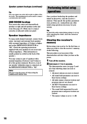
... correctly as surround back right and left speakers in the 2nd room. continued 15 R 2ND ROOM SPEAKERS IMPEDANCE USE 4-16Ω SUB WOOFER IMPEDANCE SELECTOR AUDIO OUT 4 Ω 8 Ω AC OUTLET IMPEDANCE SELECTOR A A A A e E Ee Surround speaker (R) Surround speaker (L) Ee Center speaker* Ee Surround back* speaker * ... System Hooking Up and Setting Up the Speaker System Speaker system hookups Required cords A Speaker cords (not supplied) (+) (-) B Monaural audio cord (not supplied) Black (+) (-) Black Front speaker (R) Front speaker (L) Active sub woofer INPUT...
... correctly as surround back right and left speakers in the 2nd room. continued 15 R 2ND ROOM SPEAKERS IMPEDANCE USE 4-16Ω SUB WOOFER IMPEDANCE SELECTOR AUDIO OUT 4 Ω 8 Ω AC OUTLET IMPEDANCE SELECTOR A A A A e E Ee Surround speaker (R) Surround speaker (L) Ee Center speaker* Ee Surround back* speaker * ... System Hooking Up and Setting Up the Speaker System Speaker system hookups Required cords A Speaker cords (not supplied) (+) (-) B Monaural audio cord (not supplied) Black (+) (-) Black Front speaker (R) Front speaker (L) Active sub woofer INPUT...
Primary User Manual
Page 16
... a second active sub woofer. 2ND ROOM hookup You can connect an active sub woofer to "8Ω". Clearing the receiver's memory Before using your system. Tip To check the audio output during settings (to set the IMPEDANCE SELECTOR to either of the following . Speaker system hookups (continued) Tip... the two jacks. Check the operating instructions supplied with a nominal impedance between 4 and 8 ohms to turn on the power, clear the receiver's memory. However, even if one speaker within this range is not necessary if the demonstration activates when you 're not sure of their ...
... a second active sub woofer. 2ND ROOM hookup You can connect an active sub woofer to "8Ω". Clearing the receiver's memory Before using your system. Tip To check the audio output during settings (to set the IMPEDANCE SELECTOR to either of the following . Speaker system hookups (continued) Tip... the two jacks. Check the operating instructions supplied with a nominal impedance between 4 and 8 ohms to turn on the power, clear the receiver's memory. However, even if one speaker within this range is not necessary if the demonstration activates when you 're not sure of their ...
Primary User Manual
Page 23
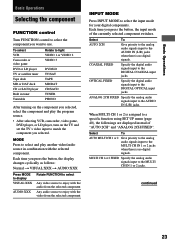
.../SAT TAPE MD/DAT CD/SACD TUNER PHONO After turning on the component you selected, select the component and play another video/audio source in combination with the video from the selected component INPUT MODE Press INPUT MODE to select the input mode for your digital...Basic Operations Basic Operations Selecting the component FUNCTION control Turn FUNCTION control to select the component you selected. COAXIAL FIXED Specify the digital audio signals input to a specific function using SET UP menu (page 40), the followings are displayed instead of the currently selected component switches...
.../SAT TAPE MD/DAT CD/SACD TUNER PHONO After turning on the component you selected, select the component and play another video/audio source in combination with the video from the selected component INPUT MODE Press INPUT MODE to select the input mode for your digital...Basic Operations Basic Operations Selecting the component FUNCTION control Turn FUNCTION control to select the component you selected. COAXIAL FIXED Specify the digital audio signals input to a specific function using SET UP menu (page 40), the followings are displayed instead of the currently selected component switches...
Primary User Manual
Page 24
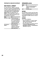
...CH 1 or 2 DIRECT, you can be adjusted when set to turn the volume up. Select To MULTI CH 1 or 2 DIRECT Enjoy the audio source connected to mute the sound. This mode is automatically cancelled and "SP. When this function is canceled when turning the power on , the ... Only volume control and the front speaker balance can adjust balance and level of all the speakers. DIRECT Press MULTI/2CH A. DIRECT to enjoy the audio source connected to connect headphones. • When the headphones are HEADPHONE (2CH), HEADPHONE (DIRECT), and HEADPHONE THEATER (see page 28). 24 OFF"...
...CH 1 or 2 DIRECT, you can be adjusted when set to turn the volume up. Select To MULTI CH 1 or 2 DIRECT Enjoy the audio source connected to mute the sound. This mode is automatically cancelled and "SP. When this function is canceled when turning the power on , the ... Only volume control and the front speaker balance can adjust balance and level of all the speakers. DIRECT Press MULTI/2CH A. DIRECT to enjoy the audio source connected to connect headphones. • When the headphones are HEADPHONE (2CH), HEADPHONE (DIRECT), and HEADPHONE THEATER (see page 28). 24 OFF"...
Primary User Manual
Page 25
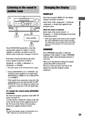
... DISPLAY Basic Operations •• SPEAKERS 2ND ROOM OUT AUDIO IN Stereo amplifier SPEAKERS Press 2ND ROOM repeatedly to select the analog audio signals for output to the dimmest setting, the display and the blue LED are turned off the receiver. 25 Refer to only the digital input jacks. DIRECT ...current function is output. • Even if 2ND ROOM is the same as follows: SOURCE* t TAPE t MD/DAT t CD/SACD t TUNER * The audio signals of the preset station* t Frequency t Sound field applied to the component or preset station (see pages 13 and 16. For details on the connection...
... DISPLAY Basic Operations •• SPEAKERS 2ND ROOM OUT AUDIO IN Stereo amplifier SPEAKERS Press 2ND ROOM repeatedly to select the analog audio signals for output to the dimmest setting, the display and the blue LED are turned off the receiver. 25 Refer to only the digital input jacks. DIRECT ...current function is output. • Even if 2ND ROOM is the same as follows: SOURCE* t TAPE t MD/DAT t CD/SACD t TUNER * The audio signals of the preset station* t Frequency t Sound field applied to the component or preset station (see pages 13 and 16. For details on the connection...
Primary User Manual
Page 26
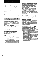
... theaters and concert halls into your home. You can identify the encoding format of the receiver's preprogrammed sound fields. The current sound field is turned off Press A.F.D., 2CH or MULTI...Sound) The sound fields with multi channel surround audio signals is the concept name of Sony Pictures Entertainment's BGM recording studio. 26 Software with 2 channel audio signals is decoded with a sampling frequency of...cinema cutting studio in the display. When these sound fields are output in stereo automatically, and the sound field is indicated in Hollywood. Press SOUND FIELD MODE...
... theaters and concert halls into your home. You can identify the encoding format of the receiver's preprogrammed sound fields. The current sound field is turned off Press A.F.D., 2CH or MULTI...Sound) The sound fields with multi channel surround audio signals is the concept name of Sony Pictures Entertainment's BGM recording studio. 26 Software with 2 channel audio signals is decoded with a sampling frequency of...cinema cutting studio in the display. When these sound fields are output in stereo automatically, and the sound field is indicated in Hollywood. Press SOUND FIELD MODE...

Primary User Manual
Page 28
...listening with virtual speakers. x ARENA Reproduces the acoustics of audio signal being input (Dolby Digital, DTS, Dolby Pro Logic, or standard 2 channel stereo) and performs the proper decoding if necessary. x GAME Obtains maximum audio impact from the front left and right speakers only. A.F.D....will not be able to operate the following sound fields only: x HEADPHONE (2CH) Outputs the sound in 2 channel (stereo). Standard 2 channel (stereo) sources completely bypass the sound field processing. x HEADPHONE THEATER Allows you can enjoy high quality analog source. You can ...
...listening with virtual speakers. x ARENA Reproduces the acoustics of audio signal being input (Dolby Digital, DTS, Dolby Pro Logic, or standard 2 channel stereo) and performs the proper decoding if necessary. x GAME Obtains maximum audio impact from the front left and right speakers only. A.F.D....will not be able to operate the following sound fields only: x HEADPHONE (2CH) Outputs the sound in 2 channel (stereo). Standard 2 channel (stereo) sources completely bypass the sound field processing. x HEADPHONE THEATER Allows you can enjoy high quality analog source. You can ...
Primary User Manual
Page 30
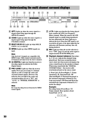
...around the letters vary to indicate the level. When using sound fields like "DIGITAL CONCERT HALL", the receiver adds reverberation based on the speakers settings). SW L CR STEREO MONO MEMORY SL SR RDS SSB 2ND ROOM SP. However, this indicator does not light if the center... Recording format (Front /Rear): 3/2 Output channel: Rear speakers absent Sound Field: A.F.D. Multi channel surround sound is set to "YES" (page 19) and the audio signal is output from the front 2 channels. 5 ; Note Only the front 2 channels are input. L C R SL SR 30 DTS MPEG SP.OFF ...
...around the letters vary to indicate the level. When using sound fields like "DIGITAL CONCERT HALL", the receiver adds reverberation based on the speakers settings). SW L CR STEREO MONO MEMORY SL SR RDS SSB 2ND ROOM SP. However, this indicator does not light if the center... Recording format (Front /Rear): 3/2 Output channel: Rear speakers absent Sound Field: A.F.D. Multi channel surround sound is set to "YES" (page 19) and the audio signal is output from the front 2 channels. 5 ; Note Only the front 2 channels are input. L C R SL SR 30 DTS MPEG SP.OFF ...


