Operating Instructions
Page 6
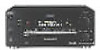
...ground wire, connect it to the appropriate jacks on the receiver. 6 White (L) White (L) Red (R) Red (R) ANTENNA AM L MD/DAT MD/DAT TV/SAT DVD/LD DVD/LD OPTICAL OPTICAL OPTICAL OPTICAL COAXIAL OUT IN IN IN IN CENTER B + U FM 75Ω COAXIAL R FRONT REAR SUB WOOFER 5.1CH... IN IN VIDEO VIDEO OUT VIDEO IN VIDEO S-VIDEO S-VIDEO OUT IN VIDEO VIDEO R - Hooking Up the Components Audio Component Hookups STR-DB940 MD/DAT deck INPUT OUTPUT LINE LINE L R ç ç Turntable OUT IN Required cords Audio cords (not supplied) When connecting a cord, be sure...
...ground wire, connect it to the appropriate jacks on the receiver. 6 White (L) White (L) Red (R) Red (R) ANTENNA AM L MD/DAT MD/DAT TV/SAT DVD/LD DVD/LD OPTICAL OPTICAL OPTICAL OPTICAL COAXIAL OUT IN IN IN IN CENTER B + U FM 75Ω COAXIAL R FRONT REAR SUB WOOFER 5.1CH... IN IN VIDEO VIDEO OUT VIDEO IN VIDEO S-VIDEO S-VIDEO OUT IN VIDEO VIDEO R - Hooking Up the Components Audio Component Hookups STR-DB940 MD/DAT deck INPUT OUTPUT LINE LINE L R ç ç Turntable OUT IN Required cords Audio cords (not supplied) When connecting a cord, be sure...
Operating Instructions
Page 7
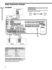
Hooking Up the Components ç STR-DB840 Turntable MD/Tape deck INPUT OUTPUT LINE LINE L R ç OUT IN Required cords ...MD/TAPE TV/SAT DVD/LD DVD/LD OPTICAL OPTICAL OPTICAL OPTICAL COAXIAL OUT IN IN IN IN CENTER B + U FM 75Ω COAXIAL R FRONT REAR SUB WOOFER 5.1CH INPUT CTRL S IN CTRL S STATUS IN DIGITAL CTRL S OUT... IMPEDANCE 4 Ω 8 Ω SELECTOR AC OUTLET R PHONO CD MD/TAPE TV/SAT DVD/LD VIDEO 2 R VIDEO 1 OUTPUT LINE L R CD player Jacks for connecting audio components Connect a Turntable CD player MD deck or tape deck To the PHONO jacks CD...
Hooking Up the Components ç STR-DB840 Turntable MD/Tape deck INPUT OUTPUT LINE LINE L R ç OUT IN Required cords ...MD/TAPE TV/SAT DVD/LD DVD/LD OPTICAL OPTICAL OPTICAL OPTICAL COAXIAL OUT IN IN IN IN CENTER B + U FM 75Ω COAXIAL R FRONT REAR SUB WOOFER 5.1CH INPUT CTRL S IN CTRL S STATUS IN DIGITAL CTRL S OUT... IMPEDANCE 4 Ω 8 Ω SELECTOR AC OUTLET R PHONO CD MD/TAPE TV/SAT DVD/LD VIDEO 2 R VIDEO 1 OUTPUT LINE L R CD player Jacks for connecting audio components Connect a Turntable CD player MD deck or tape deck To the PHONO jacks CD...
Operating Instructions
Page 8
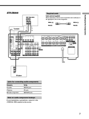
...for connecting a TV monitor You can connect your TV's audio output jacks to the TV/ SAT AUDIO IN jacks on the receiver and apply sound effects to the receiver as shown above. ANTENNA AM L MD/DAT MD/DAT ...TV/SAT DVD/LD DVD/LD OPTICAL OPTICAL OPTICAL OPTICAL COAXIAL OUT IN IN IN IN CENTER B + U FM 75&#.../LD jacks MONITOR VIDEO OUT jack VIDEO 3 INPUT jacks on the front panel 1) For STR-DB940, you are on a separate bus from the TV. Ç Ç Hooking Up the Components Video ...
...for connecting a TV monitor You can connect your TV's audio output jacks to the TV/ SAT AUDIO IN jacks on the receiver and apply sound effects to the receiver as shown above. ANTENNA AM L MD/DAT MD/DAT ...TV/SAT DVD/LD DVD/LD OPTICAL OPTICAL OPTICAL OPTICAL COAXIAL OUT IN IN IN IN CENTER B + U FM 75&#.../LD jacks MONITOR VIDEO OUT jack VIDEO 3 INPUT jacks on the front panel 1) For STR-DB940, you are on a separate bus from the TV. Ç Ç Hooking Up the Components Video ...
Operating Instructions
Page 9
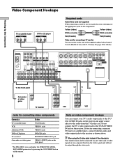
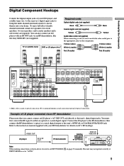
...LD IN jack. Example of LD player connected via an RF demodulator, like the Sony MOD-RF1 (not supplied). Refer to the instruction manual supplied with an RF OUT ...Hooking Up the Components Digital Component Hookups Connect the digital output jacks of your DVD player and satellite tuner (etc.) to the receiver's digital input jacks to bring the multi channel surround sound... OPTICAL OUTPUT DIGITAL OPTICAL OUTPUT DIGITAL COAXIAL AUDIO OUT L R ANTENNA AM L MD/DAT MD/DAT TV/SAT DVD/LD DVD/LD OPTICAL OPTICAL OPTICAL OPTICAL COAXIAL OUT IN IN IN IN CENTER B + U FM 75Ω ...
...LD IN jack. Example of LD player connected via an RF demodulator, like the Sony MOD-RF1 (not supplied). Refer to the instruction manual supplied with an RF OUT ...Hooking Up the Components Digital Component Hookups Connect the digital output jacks of your DVD player and satellite tuner (etc.) to the receiver's digital input jacks to bring the multi channel surround sound... OPTICAL OUTPUT DIGITAL OPTICAL OUTPUT DIGITAL COAXIAL AUDIO OUT L R ANTENNA AM L MD/DAT MD/DAT TV/SAT DVD/LD DVD/LD OPTICAL OPTICAL OPTICAL OPTICAL COAXIAL OUT IN IN IN IN CENTER B + U FM 75Ω ...

Operating Instructions
Page 10
... OUT IN ANTENNA AM L MD/DAT MD/DAT TV/SAT DVD/LD DVD/LD OPTICAL OPTICAL OPTICAL OPTICAL COAXIAL OUT IN IN IN IN CENTER B + U FM 75Ω COAXIAL R FRONT REAR SUB WOOFER 5.1CH INPUT CTRL S IN CTRL S STATUS IN DIGITAL CTRL S OUT CTRL S OUT SIGNAL GND U S-VIDEO OUT VIDEO ...your DVD (or LD player) and satellite broadcasts. ç ç Hooking Up the Components Digital Component Hookups Connect the digital output jacks of your MD or DAT deck to the receiver's digital input jack and connect the digital input jacks of your MD or DAT deck to the digital input on the...
... OUT IN ANTENNA AM L MD/DAT MD/DAT TV/SAT DVD/LD DVD/LD OPTICAL OPTICAL OPTICAL OPTICAL COAXIAL OUT IN IN IN IN CENTER B + U FM 75Ω COAXIAL R FRONT REAR SUB WOOFER 5.1CH INPUT CTRL S IN CTRL S STATUS IN DIGITAL CTRL S OUT CTRL S OUT SIGNAL GND U S-VIDEO OUT VIDEO ...your DVD (or LD player) and satellite broadcasts. ç ç Hooking Up the Components Digital Component Hookups Connect the digital output jacks of your MD or DAT deck to the receiver's digital input jack and connect the digital input jacks of your MD or DAT deck to the digital input on the...
Operating Instructions
Page 11
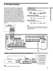
...decoder, etc., for details on speaker system hookup. Alternatively, the 5.1CH INPUT jacks can connect them directly to this receiver incorporates a multi channel decoder, it is equipped with 5.1CH OUTPUT jacks, you can be used to connect an external multi channel decoder. ANTENNA AM L MD/DAT MD/DAT TV.../SAT DVD/LD DVD/LD OPTICAL OPTICAL OPTICAL OPTICAL COAXIAL OUT IN IN IN IN CENTER B + U FM 75Ω COAXIAL R FRONT REAR SUB...
...decoder, etc., for details on speaker system hookup. Alternatively, the 5.1CH INPUT jacks can connect them directly to this receiver incorporates a multi channel decoder, it is equipped with 5.1CH OUTPUT jacks, you can be used to connect an external multi channel decoder. ANTENNA AM L MD/DAT MD/DAT TV.../SAT DVD/LD DVD/LD OPTICAL OPTICAL OPTICAL OPTICAL COAXIAL OUT IN IN IN IN CENTER B + U FM 75Ω COAXIAL R FRONT REAR SUB...
Operating Instructions
Page 12
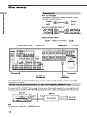
...STR-DB940 only) b To a wall outlet * The configuration, shape, and number of AC outlets on pages 26 and 27) to switch the audio signal output to which the receiver... OPTICAL OPTICAL OPTICAL COAXIAL OUT IN IN IN IN CENTER B + U FM 75Ω COAXIAL R FRONT REAR SUB WOOFER 5.1CH INPUT CTRL S IN...output the audio signal of area code U, CA only. Main room Sub room ?/1 4 • • • • 5 • • • 6• • 3 7 AUDIO AUDIO 2 8 OUT IN R Speaker (L) - + - + 1 0 • • • 9 10 Stereo...
...STR-DB940 only) b To a wall outlet * The configuration, shape, and number of AC outlets on pages 26 and 27) to switch the audio signal output to which the receiver... OPTICAL OPTICAL OPTICAL COAXIAL OUT IN IN IN IN CENTER B + U FM 75Ω COAXIAL R FRONT REAR SUB WOOFER 5.1CH INPUT CTRL S IN...output the audio signal of area code U, CA only. Main room Sub room ?/1 4 • • • • 5 • • • 6• • 3 7 AUDIO AUDIO 2 8 OUT IN R Speaker (L) - + - + 1 0 • • • 9 10 Stereo...

Operating Instructions
Page 13
..., you have a S-LINK CONTROL S-compatible Sony TV, satellite tuner, monitor, DVD player or VCR, use an audio/video/control S connecting cord (supplied) or a control S connecting cord (supplied) to the VIDEO 2 jacks on the receiver. VCR 1 TV/SAT DVD/LD VIDEO 1 * OUTPUT VIDEO OUT S-LINK IN AUDIO OUT DVD ...player S-LINK IN * OUTPUT VIDEO OUT AUDIO OUT 13 Refer to "CONTROL A1 Control System" on page 54 and the ...
..., you have a S-LINK CONTROL S-compatible Sony TV, satellite tuner, monitor, DVD player or VCR, use an audio/video/control S connecting cord (supplied) or a control S connecting cord (supplied) to the VIDEO 2 jacks on the receiver. VCR 1 TV/SAT DVD/LD VIDEO 1 * OUTPUT VIDEO OUT S-LINK IN AUDIO OUT DVD ...player S-LINK IN * OUTPUT VIDEO OUT AUDIO OUT 13 Refer to "CONTROL A1 Control System" on page 54 and the ...

Operating Instructions
Page 16
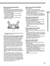
... used to connect a second active sub woofer. } }] Rear speaker (L) ] INPUT AUDIO IN Active sub woofer z To connect certain speakers to avoid excessive output on the components: + to the PRE OUT FRONT L and R jacks. For example, if you use front speakers with low maximum input rating, adjust the... SELECTOR ] ANTENNA AM L MD/DAT MD/DAT TV/SAT DVD/LD DVD/LD OPTICAL OPTICAL OPTICAL OPTICAL COAXIAL OUT IN IN IN IN CENTER B + U FM 75Ω COAXIAL R FRONT REAR SUB WOOFER 5.1CH INPUT CTRL S IN CTRL S STATUS IN DIGITAL CTRL S OUT CTRL S OUT SIGNAL GND U S-VIDEO...
... used to connect a second active sub woofer. } }] Rear speaker (L) ] INPUT AUDIO IN Active sub woofer z To connect certain speakers to avoid excessive output on the components: + to the PRE OUT FRONT L and R jacks. For example, if you use front speakers with low maximum input rating, adjust the... SELECTOR ] ANTENNA AM L MD/DAT MD/DAT TV/SAT DVD/LD DVD/LD OPTICAL OPTICAL OPTICAL OPTICAL COAXIAL OUT IN IN IN IN CENTER B + U FM 75Ω COAXIAL R FRONT REAR SUB WOOFER 5.1CH INPUT CTRL S IN CTRL S STATUS IN DIGITAL CTRL S OUT CTRL S OUT SIGNAL GND U S-VIDEO...

Operating Instructions
Page 17
... set the speaker IMPEDANCE SELECTOR to all the speakers are connected correctly. After connecting all the components, speakers, and AC power cord, output a test tone to "4Ω". If this , make sure to "4Ω". Stripped cords are touching each speaker cord do not touch ...another speaker terminal or the stripped end of the speaker cord Stripped speaker cord is usually printed on a label on the receiver, the speaker may damage the receiver. Speaker impedance To enjoy multi channel surround, connect front, center, and rear speakers with a nominal impedance between 4 and ...
... set the speaker IMPEDANCE SELECTOR to all the speakers are connected correctly. After connecting all the components, speakers, and AC power cord, output a test tone to "4Ω". If this , make sure to "4Ω". Stripped cords are touching each speaker cord do not touch ...another speaker terminal or the stripped end of the speaker cord Stripped speaker cord is usually printed on a label on the receiver, the speaker may damage the receiver. Speaker impedance To enjoy multi channel surround, connect front, center, and rear speakers with a nominal impedance between 4 and ...
Operating Instructions
Page 19
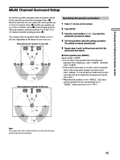
...Press ?/1 to turn on the shape of surround effects when using multi channel surround sound, select "SMALL" to activate the bass redirection circuitry and output the front channel bass frequencies from the sub woofer. • When the front speaker is set to "SMALL", the center and rear speakers ...position (A). x Front speaker size (FRONT) Initial setting : LARGE • If you desire. However, this unit lets you or to the side, depending on the receiver. 2 Press SET UP. 3 Press the cursor buttons ( or ) to select the parameter you want to adjust. 4 Turn the jog dial to "NO"). The...
...Press ?/1 to turn on the shape of surround effects when using multi channel surround sound, select "SMALL" to activate the bass redirection circuitry and output the front channel bass frequencies from the sub woofer. • When the front speaker is set to "SMALL", the center and rear speakers ...position (A). x Front speaker size (FRONT) Initial setting : LARGE • If you desire. However, this unit lets you or to the side, depending on the receiver. 2 Press SET UP. 3 Press the cursor buttons ( or ) to select the parameter you want to adjust. 4 Turn the jog dial to "NO"). The...

Operating Instructions
Page 20
...; If you do not connect rear speakers, select "NO".*3 z *1~*3 correspond to the following Dolby Pro Logic modes *1 NORMAL *2 PHANTOM *3 3 STEREO z About speaker sizes (LARGE and SMALL) Internally, the LARGE and SMALL settings for proper implementation of your rear speakers corresponds to "LARGE". Normally, ...select "LARGE". However, since bass sounds have bass frequencies output from that will be output from the front speakers (if set to "SMALL". Refer to the illustration below. • Select "SIDE" if ...
...; If you do not connect rear speakers, select "NO".*3 z *1~*3 correspond to the following Dolby Pro Logic modes *1 NORMAL *2 PHANTOM *3 3 STEREO z About speaker sizes (LARGE and SMALL) Internally, the LARGE and SMALL settings for proper implementation of your rear speakers corresponds to "LARGE". Normally, ...select "LARGE". However, since bass sounds have bass frequencies output from that will be output from the front speakers (if set to "SMALL". Refer to the illustration below. • Select "SIDE" if ...
Operating Instructions
Page 21
... listening position (C on page 19). • Do not place the center speaker farther away from your listening environment. This activates the bass redirection circuitry and outputs the LFE signals from your listening position to the rear (left or right) speaker. • Rear speaker distance can be located behind the listening position...
... listening position (C on page 19). • Do not place the center speaker farther away from your listening environment. This activates the bass redirection circuitry and outputs the LFE signals from your listening position to the rear (left or right) speaker. • Rear speaker distance can be located behind the listening position...

Operating Instructions
Page 22
... will create a fairly realistic sensation of being "inside" the screen. buttons on the remote. 22 Note The test tone cannot be adjusted in the output of the rear speakers, press the LEVEL REAR +/- on the remote. • To adjust the volume level of the sound from the listening position... note that speaker. In other words, the speaker will cause a delay in 30 Hz steps from 60 Hz to "SMALL". The frequency can be output when the receiver is not conducive to a 1 ms difference. * Models of each speaker. Likewise, the rear speakers can be set to 5.1CH INPUT. For example, ...
... will create a fairly realistic sensation of being "inside" the screen. buttons on the remote. 22 Note The test tone cannot be adjusted in the output of the rear speakers, press the LEVEL REAR +/- on the remote. • To adjust the volume level of the sound from the listening position... note that speaker. In other words, the speaker will cause a delay in 30 Hz steps from 60 Hz to "SMALL". The frequency can be output when the receiver is not conducive to a 1 ms difference. * Models of each speaker. Likewise, the rear speakers can be set to 5.1CH INPUT. For example, ...
Operating Instructions
Page 23
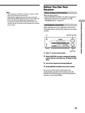
... the connections After connecting all of your listening position using the LEVEL menu (when the test tone is output, the receiver switches to turn on the receiver. FUNCTION 2 Rotate FUNCTION to select a component (program source) that you connected (e.g., CD player or tape... sure that you follow the procedure described above and adjust the speaker levels from your components to the receiver, do not obtain normal sound output after performing this procedure, look for the reason in the display during adjustment. • Although these adjustments can also be made correctly. 1/u ?/1 ...
... the connections After connecting all of your listening position using the LEVEL menu (when the test tone is output, the receiver switches to turn on the receiver. FUNCTION 2 Rotate FUNCTION to select a component (program source) that you connected (e.g., CD player or tape... sure that you follow the procedure described above and adjust the speaker levels from your components to the receiver, do not obtain normal sound output after performing this procedure, look for the reason in the display during adjustment. • Although these adjustments can also be made correctly. 1/u ?/1 ...
Operating Instructions
Page 24
...wj SPEAKERS selector" and "PHONES jack" on page 30). No sound is heard from one channel is output from a specific component. , Check that the component is connected correctly to the receiver correctly. Check the connection of headphones to the PHONES jack and set to OFF or to a position...sound no sound from the headphones, the component may not be connected to the receiver correctly. Check that all speaker cords are output from the headphones (see "Troubleshooting" on page 56. 24 If both the receiver and the component. If only one of the front speakers. , Connect a ...
...wj SPEAKERS selector" and "PHONES jack" on page 30). No sound is heard from one channel is output from a specific component. , Check that the component is connected correctly to the receiver correctly. Check the connection of headphones to the PHONES jack and set to OFF or to a position...sound no sound from the headphones, the component may not be connected to the receiver correctly. Check that all speaker cords are output from the headphones (see "Troubleshooting" on page 56. 24 If both the receiver and the component. If only one of the front speakers. , Connect a ...
Operating Instructions
Page 27
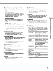
...selected component T When 5.1CH INPUT is used to select the input mode for your sub room. No signals are no sound is output when the receiver is selected DIGITAL (OPTICAL) Specify the digital audio signals input to the DIGITAL OPTICAL input jacks DIGITAL (COAXIAL) Specify the digital ...(STR-DB840)). Press MODE to display And rotate FUNCTION to select V:XXX Any video source to enjoy with the audio from the selected component A:XXX Any audio source to enjoy with the video from components connected to digital signals when there are output through the 2ND AUDIO jacks. FM...
...selected component T When 5.1CH INPUT is used to select the input mode for your sub room. No signals are no sound is output when the receiver is selected DIGITAL (OPTICAL) Specify the digital audio signals input to the DIGITAL OPTICAL input jacks DIGITAL (COAXIAL) Specify the digital ...(STR-DB840)). Press MODE to display And rotate FUNCTION to select V:XXX Any video source to enjoy with the audio from the selected component A:XXX Any audio source to enjoy with the video from components connected to digital signals when there are output through the 2ND AUDIO jacks. FM...
Operating Instructions
Page 29
A.F.D. MODE +/- For details, see "ANALOG DIRECT" on -screen (STR-DB940 only) display (page 54). Press 5.1 CH again to return to the original function. • When 5.1CH INPUT is set the receiver to automatically detect the type of audio signal being input and perform proper decoding (if necessary).... individual characters for the preset station and program source names. Auto Function Specify whether or not Sony components connected via Control A1 cords will turn off response to output sound from page 31. The indicator on or off when you can adjust the various speaker level...
A.F.D. MODE +/- For details, see "ANALOG DIRECT" on -screen (STR-DB940 only) display (page 54). Press 5.1 CH again to return to the original function. • When 5.1CH INPUT is set the receiver to automatically detect the type of audio signal being input and perform proper decoding (if necessary).... individual characters for the preset station and program source names. Auto Function Specify whether or not Sony components connected via Control A1 cords will turn off response to output sound from page 31. The indicator on or off when you can adjust the various speaker level...
Operating Instructions
Page 30
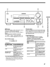
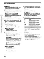
...see "Receiving Broadcasts" starting from page 43. Models of other area codes TEST TONE button Press to drive. wg Models of area code CED The following buttons operate the built-in tuner. wj SPEAKERS selector Set according to the front speakers you want to output the...CED TUNING/PTY SELECT +/- MEMORY button Press to stations broadcasting traffic announcements, news, or information program. FM MODE button If "STEREO" flashes in the display and the FM stereo reception is improved. Selecting other sound fields when the SPEAKERS selector is turned on. The EQ indicator in...
...see "Receiving Broadcasts" starting from page 43. Models of other area codes TEST TONE button Press to drive. wg Models of area code CED The following buttons operate the built-in tuner. wj SPEAKERS selector Set according to the front speakers you want to output the...CED TUNING/PTY SELECT +/- MEMORY button Press to stations broadcasting traffic announcements, news, or information program. FM MODE button If "STEREO" flashes in the display and the FM stereo reception is improved. Selecting other sound fields when the SPEAKERS selector is turned on. The EQ indicator in...

Operating Instructions
Page 32
...sound field. Selecting a Sound Field You can identify the encoding format of buttons used to enjoy surround sound LEVEL button: Press to output sound from only the front (left and right) speakers. The current sound field is automatically applied again. With the tuner, sound ... processing. EQUALIZER button: Turns the equalizer on or off Press A.F.D. z The receiver memorizes the last sound field selected for AM, FM, and all preset stations. button: Press to set the receiver to automatically detect the type of the pre-programmed sound fields according to the...
...sound field. Selecting a Sound Field You can identify the encoding format of buttons used to enjoy surround sound LEVEL button: Press to output sound from only the front (left and right) speakers. The current sound field is automatically applied again. With the tuner, sound ... processing. EQUALIZER button: Turns the equalizer on or off Press A.F.D. z The receiver memorizes the last sound field selected for AM, FM, and all preset stations. button: Press to set the receiver to automatically detect the type of the pre-programmed sound fields according to the...


