
Service Manual
Page 3
... Section (SA-WCT100 58 6-2. AMP Section (SA-WCT100 60 6-4. MAIN Section (SA-WCT100 14 5-2. Block Diagram - AMP Section (SA-WCT100 16 5-4. Block Diagram - MAIN Board (1/7) (SA-WCT100 19 5-6. MAIN Board (4/7) (SA-WCT100 22 5-9. Schematic Diagram - Printed Wiring Board - Printed Wiring Board - IO Board (SA-WCT100 28 5-15. Schematic Diagram - Printed Wiring Board - HDMI Board (Side B) (SA-WCT100 31 5-18. Printed Wiring Board - Printed Wiring Board - REMOTE Board...
... Section (SA-WCT100 58 6-2. AMP Section (SA-WCT100 60 6-4. MAIN Section (SA-WCT100 14 5-2. Block Diagram - AMP Section (SA-WCT100 16 5-4. Block Diagram - MAIN Board (1/7) (SA-WCT100 19 5-6. MAIN Board (4/7) (SA-WCT100 22 5-9. Schematic Diagram - Printed Wiring Board - Printed Wiring Board - IO Board (SA-WCT100 28 5-15. Schematic Diagram - Printed Wiring Board - HDMI Board (Side B) (SA-WCT100 31 5-18. Printed Wiring Board - Printed Wiring Board - REMOTE Board...
Service Manual
Page 5
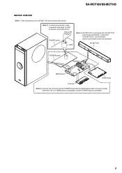
...937;/2W POWER board C903 Note 4: SA-WCT100 is operation. Note 2: In checking the board, make a capacitor discharge of MAIN board is damaged, and the POWER board is not connected, remote commander cannot be operation. If SS-MCT100 is protected. 5 SA-WCT100/SS-MCT100 SERVICE POSITION Note 1: Take... all board out from SA-WCT100 and connect each board. SS-MCT100 POWER board MAIN board HDMI board IO...
...937;/2W POWER board C903 Note 4: SA-WCT100 is operation. Note 2: In checking the board, make a capacitor discharge of MAIN board is damaged, and the POWER board is not connected, remote commander cannot be operation. If SS-MCT100 is protected. 5 SA-WCT100/SS-MCT100 SERVICE POSITION Note 1: Take... all board out from SA-WCT100 and connect each board. SS-MCT100 POWER board MAIN board HDMI board IO...
Service Manual
Page 6
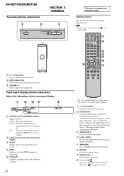
.... Then press to adjust the volume level. Note • Point the remote at the remote sensor satellite speaker. The buttons are using. 6 Thia section is being used. Press to adjust the volume. ) $, 9, Y, D or Press $, 9, Y or D to control Sony components. VOLUME + A ?/1 (on/standby) Press to select the component...as a guide during operation. You can change the factory settings of the system. ' MUTING Press to the audio input signals. SA-WCT100/SS-MCT100 Top panel (Active subwoofer) SECTION 2 GENERAL INPUT SELECTOR - E COAX/OPT Lights up according to the cable which you ...
.... Then press to adjust the volume level. Note • Point the remote at the remote sensor satellite speaker. The buttons are using. 6 Thia section is being used. Press to adjust the volume. ) $, 9, Y, D or Press $, 9, Y or D to control Sony components. VOLUME + A ?/1 (on/standby) Press to select the component...as a guide during operation. You can change the factory settings of the system. ' MUTING Press to the audio input signals. SA-WCT100/SS-MCT100 Top panel (Active subwoofer) SECTION 2 GENERAL INPUT SELECTOR - E COAX/OPT Lights up according to the cable which you ...
Service Manual
Page 13
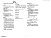
... mode. 2-8. Press the [VOLUME +] and [VOLUME -] buttons to the display. 4. appears on the fluorescent indicator tube. SA-WCT100/SS-MCT100 SA-WCT100/SS-MCT100 13 13 cator tube, then turn the power on the fluorescent indicator tube and enter the tone test mode. PUT... DMPORT check jig (Part No.: J-2501-309-A) SA-WCT100 SS-MCT100 2-9. Press the [?/1] button to select the "TONE TEST", and press the [INPUT SELECTOR] button. 3. However, once a button has been pressed, it is not connected, remote commander cannot be operation. Tone Test Procedure: 1. ...
... mode. 2-8. Press the [VOLUME +] and [VOLUME -] buttons to the display. 4. appears on the fluorescent indicator tube. SA-WCT100/SS-MCT100 SA-WCT100/SS-MCT100 13 13 cator tube, then turn the power on the fluorescent indicator tube and enter the tone test mode. PUT... DMPORT check jig (Part No.: J-2501-309-A) SA-WCT100 SS-MCT100 2-9. Press the [?/1] button to select the "TONE TEST", and press the [INPUT SELECTOR] button. 3. However, once a button has been pressed, it is not connected, remote commander cannot be operation. Tone Test Procedure: 1. ...

Service Manual
Page 17
... GENERATOR IC1006 +1.8V +1.8V REGULATOR IC3050 HDMI+3.3V +3.3V REGULATOR IC3526 SHUNT REGULATOR IC951 ISOLATOR PC902 TH901 LF901, 902 F901 LINE FILTER AC IN (TO SA-WCT100) CN871 3 SIRCS REMOTE CONTROL RECEIVER IC871 P_CONT4 65 HDMI+1.8V +1.8V REGULATOR IC3528 +3.3V REGULATOR IC3527...
... GENERATOR IC1006 +1.8V +1.8V REGULATOR IC3050 HDMI+3.3V +3.3V REGULATOR IC3526 SHUNT REGULATOR IC951 ISOLATOR PC902 TH901 LF901, 902 F901 LINE FILTER AC IN (TO SA-WCT100) CN871 3 SIRCS REMOTE CONTROL RECEIVER IC871 P_CONT4 65 HDMI+1.8V +1.8V REGULATOR IC3528 +3.3V REGULATOR IC3527...

Service Manual
Page 18
...Waveforms are indicated. • HDMI board is printed in diagrams. • Indication of transistor. SA-WCT100 - IO board HDMI board MAIN board POWER board SPOUT board SA-WCT100/SS-MCT100 18 18 REMOTE board Parts on the parts face side seen from the parts face are taken with a oscilloscope... to waveforms. • Signal path. J : AUDIO (DIGITAL) F : AUDIO (ANALOG) E : VIDEO • Circuit Boards Location - SS-MCT100 - SA-WCT100/SS-MCT100 THIS NOTE IS COMMON FOR PRINTED WIRING BOARDS AND SCHEMATIC DIAGRAMS. (In addition to ground under no mark: POWER ON • Voltages are...
...Waveforms are indicated. • HDMI board is printed in diagrams. • Indication of transistor. SA-WCT100 - IO board HDMI board MAIN board POWER board SPOUT board SA-WCT100/SS-MCT100 18 18 REMOTE board Parts on the parts face side seen from the parts face are taken with a oscilloscope... to waveforms. • Signal path. J : AUDIO (DIGITAL) F : AUDIO (ANALOG) E : VIDEO • Circuit Boards Location - SS-MCT100 - SA-WCT100/SS-MCT100 THIS NOTE IS COMMON FOR PRINTED WIRING BOARDS AND SCHEMATIC DIAGRAMS. (In addition to ground under no mark: POWER ON • Voltages are...

Service Manual
Page 34
... C252 11 (11) 1-875-654- SA-WCT100/SS-MCT100 5-20. PRINTED WIRING BOARD - REMOTE Board (SS-MCT100) - 1 2 3 4 A REMOTE BOARD IC871 GP1UE26XKOVF IC871 VCC OUT GND REMOTE CONTROL 1 3 RECEIVER B C879 10 R871 22 R872 22 L871 47uH CN871 3P 1 2 3 DGND E3.3V SIRCS C TO SA-WCT100 SA-WCT100/SS-MCT100 34 34 SPOUT Board (SA-WCT100) • See Page 18 for Circuit...
... C252 11 (11) 1-875-654- SA-WCT100/SS-MCT100 5-20. PRINTED WIRING BOARD - REMOTE Board (SS-MCT100) - 1 2 3 4 A REMOTE BOARD IC871 GP1UE26XKOVF IC871 VCC OUT GND REMOTE CONTROL 1 3 RECEIVER B C879 10 R871 22 R872 22 L871 47uH CN871 3P 1 2 3 DGND E3.3V SIRCS C TO SA-WCT100 SA-WCT100/SS-MCT100 34 34 SPOUT Board (SA-WCT100) • See Page 18 for Circuit...
Service Manual
Page 53
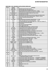
SA-WCT100/SS-MCT100 MAIN BOARD IC1002 M30626MJP-A16FPU (SYSTEM CONTROLLER) Pin No. 1 2 3 4 5 6 7 8 9 10 11 12 13 14 15 16 17 18 19 20 21 22 23 ... clock signal output to the stream processor XCEC_DI I CEC serial data input from the HDMI TV OUT connector "L" active SIRCS_IN I SIRCS signal input from the remote control receiver in the SS-MCT100 "L" active DSP_MOSI/DIR_DIN O Serial data output to the DSP and digital audio interface receiver DSP_MISO I Serial data input from...
SA-WCT100/SS-MCT100 MAIN BOARD IC1002 M30626MJP-A16FPU (SYSTEM CONTROLLER) Pin No. 1 2 3 4 5 6 7 8 9 10 11 12 13 14 15 16 17 18 19 20 21 22 23 ... clock signal output to the stream processor XCEC_DI I CEC serial data input from the HDMI TV OUT connector "L" active SIRCS_IN I SIRCS signal input from the remote control receiver in the SS-MCT100 "L" active DSP_MOSI/DIR_DIN O Serial data output to the DSP and digital audio interface receiver DSP_MISO I Serial data input from...
Service Manual
Page 62
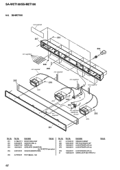
... X-2188-071-1 3-284-687-01 4-986-971-02 1-834-923-11 3-287-022-01 FRONT PANEL ASSY CUSHION, SEAL (L) SCREW (3.5) CORD (WITH CONNECTOR) (for SA-WCT100 connection) CUSHION (REMOTE PWB) 206 3-279-902-01 FOOT (8pieces, 1set) Ref. No. 207 208 SP2 SP3 Part No. 3-279-901-01 2-653-226-01 1-826-832... 207 203 not supplied 204 not supplied 206 208 not supplied not supplied 202 203 not supplied SP2 SP3 not supplied #1 203 #1 205 not supplied (REMOTE board) 203 SP4 201 Ref.
... X-2188-071-1 3-284-687-01 4-986-971-02 1-834-923-11 3-287-022-01 FRONT PANEL ASSY CUSHION, SEAL (L) SCREW (3.5) CORD (WITH CONNECTOR) (for SA-WCT100 connection) CUSHION (REMOTE PWB) 206 3-279-902-01 FOOT (8pieces, 1set) Ref. No. 207 208 SP2 SP3 Part No. 3-279-901-01 2-653-226-01 1-826-832... 207 203 not supplied 204 not supplied 206 208 not supplied not supplied 202 203 not supplied SP2 SP3 not supplied #1 203 #1 205 not supplied (REMOTE board) 203 SP4 201 Ref.

Service Manual
Page 74
...S801 1-786-650-21 SWITCH, TACTILE (I/1 0 TH901 1-805-841-21 THERMISTOR, NTC 3.0 < VARISTOR > 0 VDR901 1-805-482-11 VARISTOR REMOTE BOARD (SS-MCT100 A-1441-740-A TSW2 BOARD, COMPLETE (SA-WCT100 < CAPACITOR > C852 1-107-826-11 CERAMIC CHIP 0.1uF C853 1-107-826-11 CERAMIC CHIP 0.1uF 10% 16V 10% 16V < CONNECTOR ..., TACTILE (INPUT SELECTOR) S803 1-786-650-21 SWITCH, TACTILE (VOLUME -) S804 1-786-650-21 SWITCH, TACTILE (VOLUME 74 No. SA-WCT100/SS-MCT100 POWER REMOTE SPOUT TSW TSW2 Ref. Part No. Part No. Description 0 R914 1-243-665-11 METAL 0.05 0 R919 1-216-836-91 METAL...
...S801 1-786-650-21 SWITCH, TACTILE (I/1 0 TH901 1-805-841-21 THERMISTOR, NTC 3.0 < VARISTOR > 0 VDR901 1-805-482-11 VARISTOR REMOTE BOARD (SS-MCT100 A-1441-740-A TSW2 BOARD, COMPLETE (SA-WCT100 < CAPACITOR > C852 1-107-826-11 CERAMIC CHIP 0.1uF C853 1-107-826-11 CERAMIC CHIP 0.1uF 10% 16V 10% 16V < CONNECTOR ..., TACTILE (INPUT SELECTOR) S803 1-786-650-21 SWITCH, TACTILE (VOLUME -) S804 1-786-650-21 SWITCH, TACTILE (VOLUME 74 No. SA-WCT100/SS-MCT100 POWER REMOTE SPOUT TSW TSW2 Ref. Part No. Part No. Description 0 R914 1-243-665-11 METAL 0.05 0 R919 1-216-836-91 METAL...


