Operating Instructions
Page 1
...kg mmʣ 2- 5 102 85 67 Remote Control Panel Operation Guide 310 332.2 355 ͢ɻ RCP-1500 RCP-1501 RCP-1530 102 67 85 © 2014 Sony Corporation Printed in the U.S.A. For the customers in order to comply with the limits for use in Europe This... Environment: E4 (controlled EMC environment, ex. This equipment has been tested and found to comply with the instruction manual, may apply, See www.dtsc.ca.gov/hazardouswaste/perchlorate For the customers in Taiwan only About the network connector CAUTION...
...kg mmʣ 2- 5 102 85 67 Remote Control Panel Operation Guide 310 332.2 355 ͢ɻ RCP-1500 RCP-1501 RCP-1530 102 67 85 © 2014 Sony Corporation Printed in the U.S.A. For the customers in order to comply with the limits for use in Europe This... Environment: E4 (controlled EMC environment, ex. This equipment has been tested and found to comply with the instruction manual, may apply, See www.dtsc.ca.gov/hazardouswaste/perchlorate For the customers in Taiwan only About the network connector CAUTION...
Operating Instructions
Page 2
... 3/4) 125 (5) Inputs/outputs REMOTE CCU/CNU AUX (RCP-1500/1501 only) EXT I/O 8-pin RJ-45 (1) 8-pin multi-connector, female (1) 8-pin multi-connector, female (1) 9-pin, female (1) Supplied accessories Operation guide (1) Operation manual (CD-ROM) (1) Optional accessories External I/O connector JAE...RCP-1500 series is operating properly before use. You can purchase a new one from the Adobe website. 1 Open the index.html file in the CD-ROM. 2 Select and click on the manual that the unit is a remote control panel for important information and complete terms and conditions of Sony...
... 3/4) 125 (5) Inputs/outputs REMOTE CCU/CNU AUX (RCP-1500/1501 only) EXT I/O 8-pin RJ-45 (1) 8-pin multi-connector, female (1) 8-pin multi-connector, female (1) 9-pin, female (1) Supplied accessories Operation guide (1) Operation manual (CD-ROM) (1) Optional accessories External I/O connector JAE...RCP-1500 series is operating properly before use. You can purchase a new one from the Adobe website. 1 Open the index.html file in the CD-ROM. 2 Select and click on the manual that the unit is a remote control panel for important information and complete terms and conditions of Sony...
Operation Guide
Page 9
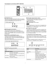
... not supplied even if the button is active, and cannot be assigned to turn its button is on changes the iris indication to the operation manual of the device of the function on which IRIS/MB is pressed. However, IRIS and master black are for CCU output. These were formerly the... an OFF indication is off displays the iris value, and the state of the BARS button takes priority for various functions. Camera/panel control block (RCP-1500/1501) a STANDARD button This button is lit.
... not supplied even if the button is active, and cannot be assigned to turn its button is on changes the iris indication to the operation manual of the device of the function on which IRIS/MB is pressed. However, IRIS and master black are for CCU output. These were formerly the... an OFF indication is off displays the iris value, and the state of the BARS button takes priority for various functions. Camera/panel control block (RCP-1500/1501) a STANDARD button This button is lit.

Operation Guide
Page 10
... adjustment. a AUTO SETUP buttons and START/BREAK button Pressing one of the connection destination. 4 AUTO SETUP block These buttons are displayed, refer to the operation manual of the device of the following buttons and then pressing the START/BREAK button runs the corresponding automatic adjustment function. When this function is ON...
... adjustment. a AUTO SETUP buttons and START/BREAK button Pressing one of the connection destination. 4 AUTO SETUP block These buttons are displayed, refer to the operation manual of the device of the following buttons and then pressing the START/BREAK button runs the corresponding automatic adjustment function. When this function is ON...

Operation Guide
Page 11
... to the spare buttons. Saturation function 11 A function is enabled when its light off when the button is displayed, refer to the operation manual of the device of the camera to CLS. Lighting state Meaning On The power is disconnected. It is supplied when the button is the... control the control panels that are only enabled on control panels on the screen (corresponds to turn its button is off . Camera/panel control block (RCP-1530) a PARA (parallel control) button This is pressed. Pressing it is lit. 1 Power/output signal selection block c CLOSE (iris close mode is ...
... to the spare buttons. Saturation function 11 A function is enabled when its light off when the button is displayed, refer to the operation manual of the device of the camera to CLS. Lighting state Meaning On The power is disconnected. It is supplied when the button is the... control the control panels that are only enabled on control panels on the screen (corresponds to turn its button is off . Camera/panel control block (RCP-1530) a PARA (parallel control) button This is pressed. Pressing it is lit. 1 Power/output signal selection block c CLOSE (iris close mode is ...

Operation Guide
Page 12
... out when adjustment is for automatically adjusting the camera. For details on for what kind of image output characters are displayed, refer to the operation manual of the device of the button switches to the next page (a long press switches to an effective hue. b WHITE (auto white balance) button This button...
... out when adjustment is for automatically adjusting the camera. For details on for what kind of image output characters are displayed, refer to the operation manual of the device of the button switches to the next page (a long press switches to an effective hue. b WHITE (auto white balance) button This button...

Operation Guide
Page 17
...automatically in the following cases. • During power up • When the active status of the number lights in green. Adjustment block (RCP-1500) 1 White balance/black balance adjustment block a ABSOLUTE button This button changes the mode for the camera controlled by pressing the FLARE button &#..., see page 44. 2 Iris/master control black adjustment block a Camera number/tally display window This window displays an amber number for manual adjustment using the WHITE, BLACK, FLARE, DETAIL, and assignable knobs between flare balance and black balance by the control panel. The knobs...
...automatically in the following cases. • During power up • When the active status of the number lights in green. Adjustment block (RCP-1500) 1 White balance/black balance adjustment block a ABSOLUTE button This button changes the mode for the camera controlled by pressing the FLARE button &#..., see page 44. 2 Iris/master control black adjustment block a Camera number/tally display window This window displays an amber number for manual adjustment using the WHITE, BLACK, FLARE, DETAIL, and assignable knobs between flare balance and black balance by the control panel. The knobs...

Operation Guide
Page 18
...is not lit. When the IRIS RELATIVE button is not lit, the indicators light dimly to the iris setting. Sets the lower limit for manually adjusting the master black. D EXT: Lights when the digital extender function is displayed. A variable amount can finely adjust the reference value ... range set by the SENS and COARSE knobs. i Iris indicators The corresponding LED lights according to display the upper and lower limits of manual adjustment. Press the switch axially to output preview key signals from OPEN to light. Also see the table "Iris Adjustment Functions", (page ...
...is not lit. When the IRIS RELATIVE button is not lit, the indicators light dimly to the iris setting. Sets the lower limit for manually adjusting the master black. D EXT: Lights when the digital extender function is displayed. A variable amount can finely adjust the reference value ... range set by the SENS and COARSE knobs. i Iris indicators The corresponding LED lights according to display the upper and lower limits of manual adjustment. Press the switch axially to output preview key signals from OPEN to light. Also see the table "Iris Adjustment Functions", (page ...

Operation Guide
Page 19
...is lit, and absolute value mode is enabled when the button is lit. Adjustment block (RCP-1501) 1 White balance/black balance adjustment block a ABSOLUTE button This button changes the mode for manual adjustment using the WHITE, BLACK, FLARE, DETAIL, and assignable knobs between flare balance and ...ACTIVE button also causes this button is not lit. 19 c IRIS RELATIVE button This button changes the manual adjustment mode of the panel has changed with the RCP Assign settings b WHITE (manual white balance) knobs These knobs allow you to right. e DETAIL knob This knob adjusts the detail level...
...is lit, and absolute value mode is enabled when the button is lit. Adjustment block (RCP-1501) 1 White balance/black balance adjustment block a ABSOLUTE button This button changes the mode for manual adjustment using the WHITE, BLACK, FLARE, DETAIL, and assignable knobs between flare balance and ...ACTIVE button also causes this button is not lit. 19 c IRIS RELATIVE button This button changes the manual adjustment mode of the panel has changed with the RCP Assign settings b WHITE (manual white balance) knobs These knobs allow you to right. e DETAIL knob This knob adjusts the detail level...

Operation Guide
Page 20
...to the camera, a black number is displayed in green. Sets the upper limit for the IRIS knob. i MASTER BLACK knob This knob is for manually adjusting the master black. D EXT: Lights when the digital extender function is used iris position, it is displayed. e SENS (iris adjustment range)... knob This knob is for manually adjusting the iris in relative values within the variable range set . (See page 37) Adjusts the iris in absolute value mode. f COARSE (iris ...
...to the camera, a black number is displayed in green. Sets the upper limit for the IRIS knob. i MASTER BLACK knob This knob is for manually adjusting the master black. D EXT: Lights when the digital extender function is used iris position, it is displayed. e SENS (iris adjustment range)... knob This knob is for manually adjusting the iris in relative values within the variable range set . (See page 37) Adjusts the iris in absolute value mode. f COARSE (iris ...

Operation Guide
Page 21
... In absolute value mode, a knob indication value becomes that setting value. a Camera number/tally display window This window displays an amber number for manual adjustment using the WHITE, BLACK, FLARE, DETAIL, and assignable knobs between flare balance and black balance by the control panel. They adjust the R,... in the following cases. • During power up • When the active status of the panel has changed with the RCP Assign settings b WHITE (manual white balance) knobs These knobs allow you to the camera, a black number is displayed and the background of the BLACK/ FLARE...
... In absolute value mode, a knob indication value becomes that setting value. a Camera number/tally display window This window displays an amber number for manual adjustment using the WHITE, BLACK, FLARE, DETAIL, and assignable knobs between flare balance and black balance by the control panel. They adjust the R,... in the following cases. • During power up • When the active status of the panel has changed with the RCP Assign settings b WHITE (manual white balance) knobs These knobs allow you to the camera, a black number is displayed and the background of the BLACK/ FLARE...

Operation Guide
Page 22
..."" (page 84). You can finely adjust the reference value for auto adjustment of the iris. h IRIS RELATIVE button This button changes the manual adjustment mode of a "Memory Stick Duo." The setting value is not lit, the indicators light dimly to CLOSE. Data is for adjusting ...This window displays the master black setting value. When the IRIS RELATIVE button is displayed in absolute value mode. Sets the lower limit for manually adjusting the iris in the master black display window. 3 "Memory Stick Duo" insertion block a Access indicator This indicates the status of...
..."" (page 84). You can finely adjust the reference value for auto adjustment of the iris. h IRIS RELATIVE button This button changes the manual adjustment mode of a "Memory Stick Duo." The setting value is not lit, the indicators light dimly to CLOSE. Data is for adjusting ...This window displays the master black setting value. When the IRIS RELATIVE button is displayed in absolute value mode. Sets the lower limit for manually adjusting the iris in the master black display window. 3 "Memory Stick Duo" insertion block a Access indicator This indicates the status of...

Operation Guide
Page 38
... screen appears. 4 Press [Mode]. Press [Preview] to the Category Select screen. Maintenance Engineer Mode Exit Camera RPN Lens CCU SD Adjusting 4 Press [RPN]. RCP Mode Engineer Mode Exit Screen Saver Panel Active PIX/WF Preview Matrix Gate Extend Call 1 Enter engineer mode. (page 51) Security Engineer Mode Exit Page...affect the pixels of screen saver. The Mode screen appears. The RPN Correction screen appears. Perform the following settings can also perform correction manually to reduce the white dots. 2 Press [Exit] to return to display a preview of the settings.
... screen appears. 4 Press [Mode]. Press [Preview] to the Category Select screen. Maintenance Engineer Mode Exit Camera RPN Lens CCU SD Adjusting 4 Press [RPN]. RCP Mode Engineer Mode Exit Screen Saver Panel Active PIX/WF Preview Matrix Gate Extend Call 1 Enter engineer mode. (page 51) Security Engineer Mode Exit Page...affect the pixels of screen saver. The Mode screen appears. The RPN Correction screen appears. Perform the following settings can also perform correction manually to reduce the white dots. 2 Press [Exit] to return to display a preview of the settings.

Operation Guide
Page 59
.... The phase of this channel for which the signal can be added, refer to the range of the corresponding device. Adds a gate signal to the manual of this channel is effective. For the output connector for which Skin DTL is adjusted automatically. This can be common to the... manual of each channel. Allows adjustment of the contour correction level of the set with the setting of the corresponding device. Allows up to three channels ...
.... The phase of this channel for which the signal can be added, refer to the range of the corresponding device. Adds a gate signal to the manual of this channel is effective. For the output connector for which Skin DTL is adjusted automatically. This can be common to the... manual of each channel. Allows adjustment of the contour correction level of the set with the setting of the corresponding device. Allows up to three channels ...

Operation Guide
Page 60
... of the R channel in the second channel of the G channel and B channel. Sets the third channel of Skin DTL. When this in response to the manual of the B channel and G channel. 60 For the output connector for Skin DTL in the minus direction makes pictures soft. Corrects the signal of the...
... of the R channel in the second channel of the G channel and B channel. Sets the third channel of Skin DTL. When this in response to the manual of the B channel and G channel. 60 For the output connector for Skin DTL in the minus direction makes pictures soft. Corrects the signal of the...

Operation Guide
Page 61
... to make adjusting the knee point easy. Links R, G, and B and adjusts them simultaneously. Changes color reproduction for which the signal can be added, see the manual of all the matrix functions. This can be common to their initial states. Selects the matrix provided for which black gamma is enabled. 61 Sets...
... to make adjusting the knee point easy. Links R, G, and B and adjusts them simultaneously. Changes color reproduction for which the signal can be added, see the manual of all the matrix functions. This can be common to their initial states. Selects the matrix provided for which black gamma is enabled. 61 Sets...
Operation Guide
Page 86
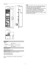
RCP-1530 80 (3 1/4) 2- 5 (7/32) 125 (5) 67 (2 3/4) Note Always verify that the unit is operating properly before use. SONY WILL NOT BE LIABLE FOR DAMAGES OF ANY KIND INCLUDING, BUT NOT LIMITED TO, COMPENSATION OR ... 67 (2 3/4) 125 (5) Inputs/outputs REMOTE 8-pin RJ-45 (1) CCU/CNU 8-pin multi-connector, female (1) AUX (RCP-1500/1501 only) 8-pin multi-connector, female (1) EXT I/O 9-pin, female (1) Supplied accessories Operation guide (1) Operation manual (CD-ROM) (1) Optional accessories External I/O connector JAE DE-9PF-N 1-568-182-11 CCA-5-3 remote cable (3 m) CCA-5-...
RCP-1530 80 (3 1/4) 2- 5 (7/32) 125 (5) 67 (2 3/4) Note Always verify that the unit is operating properly before use. SONY WILL NOT BE LIABLE FOR DAMAGES OF ANY KIND INCLUDING, BUT NOT LIMITED TO, COMPENSATION OR ... 67 (2 3/4) 125 (5) Inputs/outputs REMOTE 8-pin RJ-45 (1) CCU/CNU 8-pin multi-connector, female (1) AUX (RCP-1500/1501 only) 8-pin multi-connector, female (1) EXT I/O 9-pin, female (1) Supplied accessories Operation guide (1) Operation manual (CD-ROM) (1) Optional accessories External I/O connector JAE DE-9PF-N 1-568-182-11 CCA-5-3 remote cable (3 m) CCA-5-...

Operation Guide
Page 87
Sony Corporation expressly prohibits the duplication of any portion of this manual or the use by the purchasers of Sony Corporation. The material contained in this manual consists of information that is the property of Sony Corporation and is intended solely for use thereof for any purpose other than the operation or maintenance of the equipment described in this manual without the express written permission of the equipment described in this manual.
Sony Corporation expressly prohibits the duplication of any portion of this manual or the use by the purchasers of Sony Corporation. The material contained in this manual consists of information that is the property of Sony Corporation and is intended solely for use thereof for any purpose other than the operation or maintenance of the equipment described in this manual without the express written permission of the equipment described in this manual.
