
Service Manual
Page 1
... the stylus tip is the stereo turntable in ) (w/h/d) 10 kg (22 lbs) Supplied Accessories Platter (2) Slip mat (2) Dust cover (with hinges) (2) Counterweight (2) Cartridge and headshell (2) 45 adaptor (2) Audio cord (with detachable headshell 230 mm 15 mm 4 g (min.) to change without notice. 9-929-553-12 2001F0200-1 © 2001.6 Sony Corporation Home Audio Company Shinagawa Tec Service Manual Production Group STEREO TURNTABLE SYSTEM...
... the stylus tip is the stereo turntable in ) (w/h/d) 10 kg (22 lbs) Supplied Accessories Platter (2) Slip mat (2) Dust cover (with hinges) (2) Counterweight (2) Cartridge and headshell (2) 45 adaptor (2) Audio cord (with detachable headshell 230 mm 15 mm 4 g (min.) to change without notice. 9-929-553-12 2001F0200-1 © 2001.6 Sony Corporation Home Audio Company Shinagawa Tec Service Manual Production Group STEREO TURNTABLE SYSTEM...

Service Manual
Page 2
...SONY PARTS WHOSE PART NUMBERS APPEAR AS SHOWN IN THIS MANUAL OR IN SUPPLEMENTS PUBLISHED BY SONY. 2 A) TABLE OF CONTENTS 1. Cabinet Section 12 4. Using an AC voltmeter to use these instruments. 2. COMPONENTS IDENTIFIED BY MARK 0 OR DOTTED LINE WITH MARK 0 ON THE SCHEMATIC DIAGRAMS AND IN THE PARTS LIST ARE CRITICAL TO SAFE OPERATION. A. Follow the manufacturers' instructions... 11 3-2. SAFETY CHECK-OUT After correcting the original service problem, perform the following safety checks before releasing the set to the customer: Check the antenna terminals, metal trim...
...SONY PARTS WHOSE PART NUMBERS APPEAR AS SHOWN IN THIS MANUAL OR IN SUPPLEMENTS PUBLISHED BY SONY. 2 A) TABLE OF CONTENTS 1. Cabinet Section 12 4. Using an AC voltmeter to use these instruments. 2. COMPONENTS IDENTIFIED BY MARK 0 OR DOTTED LINE WITH MARK 0 ON THE SCHEMATIC DIAGRAMS AND IN THE PARTS LIST ARE CRITICAL TO SAFE OPERATION. A. Follow the manufacturers' instructions... 11 3-2. SAFETY CHECK-OUT After correcting the original service problem, perform the following safety checks before releasing the set to the customer: Check the antenna terminals, metal trim...
Service Manual
Page 3
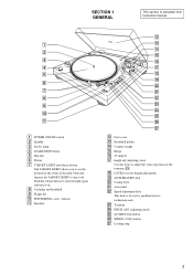
... raise the light again and turn it on. 8 Cartridge and headshell 9 Finger lift q; Cueing lever wa Arm stand ws Speed-adjustment hole This hole is extracted from instruction manual. 1 2 3 4 5 6 7 8 9 0 qa 1 POWER ON/OFF switch 2 Spindle ... stylus in the dark. wd Tonearm wf PITCH ADJ. (adjusting) knob wg QUARTZ lock button wh SPEED (33/45) button wj Locking ring 3 Push the release button to turn ...it off. PITCH BEND + and - SECTION 1 GENERAL This section is for height adjustment) ql ANTI-SKATING dial w; qk LOCK lever (for use by qualified service technicians only...
... raise the light again and turn it on. 8 Cartridge and headshell 9 Finger lift q; Cueing lever wa Arm stand ws Speed-adjustment hole This hole is extracted from instruction manual. 1 2 3 4 5 6 7 8 9 0 qa 1 POWER ON/OFF switch 2 Spindle ... stylus in the dark. wd Tonearm wf PITCH ADJ. (adjusting) knob wg QUARTZ lock button wh SPEED (33/45) button wj Locking ring 3 Push the release button to turn ...it off. PITCH BEND + and - SECTION 1 GENERAL This section is for height adjustment) ql ANTI-SKATING dial w; qk LOCK lever (for use by qualified service technicians only...

Service Manual
Page 4
... the Turntable Before attempting to play any records, be sure to complete the following steps to "0." The numbers on the bottom of 4 grams, which is aligned to the index line. Failure to complete these adjustments will remain level with the index line. Take care not to 1. You can set a tracking force of 3 to 7 grams. Turn the...
... the Turntable Before attempting to play any records, be sure to complete the following steps to "0." The numbers on the bottom of 4 grams, which is aligned to the index line. Failure to complete these adjustments will remain level with the index line. Take care not to 1. You can set a tracking force of 3 to 7 grams. Turn the...

Service Manual
Page 5
... Press Bx START/STOP. Turn the POWER switch on the stereo component system or amplifier. buttons" on page 8). 9 If you wish, you can also use the respective channel fader on the mixer, or the volume control on the mixer and amplifier to ON also. 3 Set PITCH ADJ. knob does ...stylus will descend slowly to the record and play an another selection playing on the record. 7 Set the cueing lever to ground under no mark : Power on the other turntable. buttons to change of the selection on • Voltages are taken with respect to the down the + or - knob is turned...
... Press Bx START/STOP. Turn the POWER switch on the stereo component system or amplifier. buttons" on page 8). 9 If you wish, you can also use the respective channel fader on the mixer, or the volume control on the mixer and amplifier to ON also. 3 Set PITCH ADJ. knob does ...stylus will descend slowly to the record and play an another selection playing on the record. 7 Set the cueing lever to ground under no mark : Power on the other turntable. buttons to change of the selection on • Voltages are taken with respect to the down the + or - knob is turned...

Service Manual
Page 6
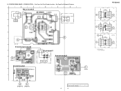
PS-DJ9000 2-2. MAIN SECTION - • See Page 8 and 9 for Printed Wiring Boards. (Page 7) (Page 7) L003, L004, L005, L006: Exchange all the four when even this one diode breaks in either one. (Page 7) (Page 7) 6 6 (Page 7) SLIDE SW (Page 7) SCHEMATIC DIAGRAM -
PS-DJ9000 2-2. MAIN SECTION - • See Page 8 and 9 for Printed Wiring Boards. (Page 7) (Page 7) L003, L004, L005, L006: Exchange all the four when even this one diode breaks in either one. (Page 7) (Page 7) 6 6 (Page 7) SLIDE SW (Page 7) SCHEMATIC DIAGRAM -

Service Manual
Page 7
MOTOR SECTION - • See Page 10 for Printed Wiring Boards. (Page 6) (Page 6) (Page 6) PS-DJ9000 (Page 6) 7 7 SCHEMATIC DIAGRAM - 2-3.
MOTOR SECTION - • See Page 10 for Printed Wiring Boards. (Page 6) (Page 6) (Page 6) PS-DJ9000 (Page 6) 7 7 SCHEMATIC DIAGRAM - 2-3.

Service Manual
Page 8
... OGI 1 E E E 10 1 14 14 8 1 7 K A K 14 8 1 7 E 14 8 1 7 14 8 14 8 7 1 7 1 7 G B (Page 9) (Page 10) A (Page 10) F (Page 9) E (Page 9) 8 8 There are a few cases that the part isn't mounted in model is printed on diagram. PS-DJ9000 2-4. PRINTED WIRING BOARD - MAIN SECTION - • See Page 5 for Circut Boards Location. • See Page 6 for Schematic Diagram. 1 2 3 4 5 6 7 8 9 MAIN BOARD A 28 15...
... OGI 1 E E E 10 1 14 14 8 1 7 K A K 14 8 1 7 E 14 8 1 7 14 8 14 8 7 1 7 1 7 G B (Page 9) (Page 10) A (Page 10) F (Page 9) E (Page 9) 8 8 There are a few cases that the part isn't mounted in model is printed on diagram. PS-DJ9000 2-4. PRINTED WIRING BOARD - MAIN SECTION - • See Page 5 for Circut Boards Location. • See Page 6 for Schematic Diagram. 1 2 3 4 5 6 7 8 9 MAIN BOARD A 28 15...
Service Manual
Page 9
... B E,MX C 5 AEP, UK PAUSE/START BOARD D G (Page 8) E POWER BOARD F 09 D E (Page 10) (Page 8) 4 LED BOARD LD06 LD05 LD03 LD04 STROBO LAMP LED SW BOARD F (Page 8) There are a few cases that the part isn't mounted in model is printed on diagram. 9 9 PS-DJ9000 US POWER TRANSFORMER 4 C (Page 10) POWER TRANSFORMER 4 * 5 * POWER TRANSFORMER 4 E, MX C (Page 10) AEP, UK C (Page 10...
... B E,MX C 5 AEP, UK PAUSE/START BOARD D G (Page 8) E POWER BOARD F 09 D E (Page 10) (Page 8) 4 LED BOARD LD06 LD05 LD03 LD04 STROBO LAMP LED SW BOARD F (Page 8) There are a few cases that the part isn't mounted in model is printed on diagram. 9 9 PS-DJ9000 US POWER TRANSFORMER 4 C (Page 10) POWER TRANSFORMER 4 * 5 * POWER TRANSFORMER 4 E, MX C (Page 10) AEP, UK C (Page 10...

Service Manual
Page 10
MOTOR BOARD A (Page 8) • Semiconductor Location Ref. Location D1 A-4 D4 B-4 D5 C-4 D6 C-4 D7 C-4 D8 C-4 D9 C-4 D10 C-4 D11 C-3 D12 C-3 D13 C-3 ZD1 C-4 IC1 B-4 IC3 B-3 IC4 A-3 Q3 A-4 Q4 A-4 B (Page 8) DC (Page 9) (Page 9) 10 10 No. PS-DJ9000 2-6. PRINTED WIRING BOARD - MOTOR SECTION - • See Page 5 for Circut Boards Location. • See Page 7 for Schematic Diagram.
MOTOR BOARD A (Page 8) • Semiconductor Location Ref. Location D1 A-4 D4 B-4 D5 C-4 D6 C-4 D7 C-4 D8 C-4 D9 C-4 D10 C-4 D11 C-3 D12 C-3 D13 C-3 ZD1 C-4 IC1 B-4 IC3 B-3 IC4 A-3 Q3 A-4 Q4 A-4 B (Page 8) DC (Page 9) (Page 9) 10 10 No. PS-DJ9000 2-6. PRINTED WIRING BOARD - MOTOR SECTION - • See Page 5 for Circut Boards Location. • See Page 7 for Schematic Diagram.
Service Manual
Page 11
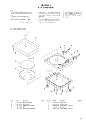
The components identified by mark 0 or dotted line with part number specified. 3-1. No. 6 7 8 9 10 Part No. BOTTOM SECTION 1 2 3 3 4 7 6 8 8 7 6 5 not supplied Ref. Replace only with mark 0 are critical for routine service. No. 1 2 3 4 5 Part No. Description 4-231-235-01 HINGE ASSY 4-231-209-01 PLASTIC, ... since they may have some difference from the original one. • Color Indication of the electrical parts list. NOTE: • -XX and -X mean standardized parts, so they are seldom required for safety. Description 4-231-219-01 PLATE(ALUMINUM) 4-231-226-...
The components identified by mark 0 or dotted line with part number specified. 3-1. No. 6 7 8 9 10 Part No. BOTTOM SECTION 1 2 3 3 4 7 6 8 8 7 6 5 not supplied Ref. Replace only with mark 0 are critical for routine service. No. 1 2 3 4 5 Part No. Description 4-231-235-01 HINGE ASSY 4-231-209-01 PLASTIC, ... since they may have some difference from the original one. • Color Indication of the electrical parts list. NOTE: • -XX and -X mean standardized parts, so they are seldom required for safety. Description 4-231-219-01 PLATE(ALUMINUM) 4-231-226-...

Service Manual
Page 12
...supplied 60 not 59 supplied not supplied 55 not supplied 73 57 72 61 72 62 not supplied (POWER board) 70 not supplied (RELAY board) 69 not supplied (PAUSE/START board) not supplied 54 53 ...not supplied (MAIN board) Ref. No. 64 65 66 66 67 68 69 70 72 73 74 T1 T1 T1 Part No. Description A-4412-592-A MOTOR BOARD, COMPLETE 4-231-231-01 TERGET (LIGHT) ASSY 4-231-232-01 BASE ...4-232-018-01 BASE ASSY, KNOB (US,MX,E) 4-231-230-01 ARM ASSY, TONE Remark 1-251-931-11 CARTRIDGE (INCLUDING STYLUS) 4-231-511-01 SHELL ASSY, HEAD 4-231-239-01 WEIGHT ASSY, COUNTER 4-231-233-01 BASE ASSY, TONE ...
...supplied 60 not 59 supplied not supplied 55 not supplied 73 57 72 61 72 62 not supplied (POWER board) 70 not supplied (RELAY board) 69 not supplied (PAUSE/START board) not supplied 54 53 ...not supplied (MAIN board) Ref. No. 64 65 66 66 67 68 69 70 72 73 74 T1 T1 T1 Part No. Description A-4412-592-A MOTOR BOARD, COMPLETE 4-231-231-01 TERGET (LIGHT) ASSY 4-231-232-01 BASE ...4-232-018-01 BASE ASSY, KNOB (US,MX,E) 4-231-230-01 ARM ASSY, TONE Remark 1-251-931-11 CARTRIDGE (INCLUDING STYLUS) 4-231-511-01 SHELL ASSY, HEAD 4-231-239-01 WEIGHT ASSY, COUNTER 4-231-233-01 BASE ASSY, TONE ...

Service Manual
Page 13
...set. • -XX and -X mean standardized parts, so they may be anticipated when ordering these items. • SEMICONDUCTORS In each case, u: µ, for routine service. uPD. . : µPD. . • CAPACITORS uF: µF • COILS uH: µH The components identified by reference number, please include the board. • Abbreviation MX:Mexican Model... LED SW BOARD Ref. SECTION 4 ELECTRICAL PARTS LIST LED LED SW MAIN NOTE: • Due to standardization, replacements in the parts list may have some difference from the parts specified in ohms. METAL: Metal-film resistor....
...set. • -XX and -X mean standardized parts, so they may be anticipated when ordering these items. • SEMICONDUCTORS In each case, u: µ, for routine service. uPD. . : µPD. . • CAPACITORS uF: µF • COILS uH: µH The components identified by reference number, please include the board. • Abbreviation MX:Mexican Model... LED SW BOARD Ref. SECTION 4 ELECTRICAL PARTS LIST LED LED SW MAIN NOTE: • Due to standardization, replacements in the parts list may have some difference from the parts specified in ohms. METAL: Metal-film resistor....

Service Manual
Page 15
Part No. No. SW10 1-570-245-11 SWITCH, MICRO (Bx START STOP POWER BOARD < CAPACITOR > C57 1-164-159-11 CERAMIC C58 1-164-159-11 CERAMIC C59 1-126-935-11 ELECT C65 1-164-159-11 CERAMIC C69 1-126-942-...-234-01 SOCKET ASSY AC 1-435-743-11 TRANSFORMER, POWER (US,MX) 1-435-744-11 TRANSFORMER, POWER (AEP,UK) 1-435-745-11 TRANSFORMER, POWER (E) Description Remark The components identified by mark 0 or dotted line with part number specified. 15 PAUSE/START POWER RELAY TONE ARM Ref. No. Replace only with mark 0 are critical for safety. Description PAUSE...
Part No. No. SW10 1-570-245-11 SWITCH, MICRO (Bx START STOP POWER BOARD < CAPACITOR > C57 1-164-159-11 CERAMIC C58 1-164-159-11 CERAMIC C59 1-126-935-11 ELECT C65 1-164-159-11 CERAMIC C69 1-126-942-...-234-01 SOCKET ASSY AC 1-435-743-11 TRANSFORMER, POWER (US,MX) 1-435-744-11 TRANSFORMER, POWER (AEP,UK) 1-435-745-11 TRANSFORMER, POWER (E) Description Remark The components identified by mark 0 or dotted line with part number specified. 15 PAUSE/START POWER RELAY TONE ARM Ref. No. Replace only with mark 0 are critical for safety. Description PAUSE...

Service Manual
Page 16
PS-DJ9000 REVISION HISTORY Clicking the version allows you to jump to the revised page. Also, clicking the version at the upper right on the revised page allows you to jump to the next revised page. Ver. Date Description of Revision 1.1 2001.06 Correction of specifications and exploded views (74). (SPM-01017) 1.0 2000.10 New.
PS-DJ9000 REVISION HISTORY Clicking the version allows you to jump to the revised page. Also, clicking the version at the upper right on the revised page allows you to jump to the next revised page. Ver. Date Description of Revision 1.1 2001.06 Correction of specifications and exploded views (74). (SPM-01017) 1.0 2000.10 New.


