
Operation Guide
Page 1
... AA) alkaline batteries Approx.350 g (10 oz)(including the supplied rechargable nickel-metal hydride batteries) CORDLESS STEREO HEADPHONES 9-873-527-02 2002C0200-1 © 2002.03 Sony Corporation Personal Audio Company Published by Sony Engineering Corporation MDR-IF8000 SERVICE MANUAL Ver 1.1 2002.03 US Model Canadian Model AEP Model UK Model •...
... AA) alkaline batteries Approx.350 g (10 oz)(including the supplied rechargable nickel-metal hydride batteries) CORDLESS STEREO HEADPHONES 9-873-527-02 2002C0200-1 © 2002.03 Sony Corporation Personal Audio Company Published by Sony Engineering Corporation MDR-IF8000 SERVICE MANUAL Ver 1.1 2002.03 US Model Canadian Model AEP Model UK Model •...

Operation Guide
Page 2
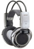
... Section 4 2-5. RX2 Section (1/2 11 4-6. ELECTRICAL PARTS LIST 16 LOCATING THE CONTROLS 5 4 3 SECTION 1 GENERAL This section is extracted from instruction manual. 6 7 1 8 2 9 1 1 Infrared sensor There are infrared sensors in a pair. TABLE OF CONTENTS 1. DISASSEMBLY 2-1. DIAGRAMS 4-1. Printed Wiring...(R 3 2-2. Block Diagrams 7 4-2. RX1 Section 9 4-4. PD1 Board 4 2-4. ELECTRICAL ADJUSTMENTS 6 4. Schematic Diagram - Repair MDR-IF8000 and DP-IF8000 in two locations on the headphones. 4 POWER indicator By pulling up the lid to open it to ON when the output ...
... Section 4 2-5. RX2 Section (1/2 11 4-6. ELECTRICAL PARTS LIST 16 LOCATING THE CONTROLS 5 4 3 SECTION 1 GENERAL This section is extracted from instruction manual. 6 7 1 8 2 9 1 1 Infrared sensor There are infrared sensors in a pair. TABLE OF CONTENTS 1. DISASSEMBLY 2-1. DIAGRAMS 4-1. Printed Wiring...(R 3 2-2. Block Diagrams 7 4-2. RX1 Section 9 4-4. PD1 Board 4 2-4. ELECTRICAL ADJUSTMENTS 6 4. Schematic Diagram - Repair MDR-IF8000 and DP-IF8000 in two locations on the headphones. 4 POWER indicator By pulling up the lid to open it to ON when the output ...

Operation Guide
Page 6
...65 1 5 IC101 10 15 20 25 16 R104 C108 C116 55 50 40 35 31 R153 R136 R126 R107 R105 C107 Procedure 1. MDR-IF8000 SECTION 3 ELECTRICAL ADJUSTMENT 0dB=0.775V CAUTION: 1. Adjust the spectrum analyzer output waveform by rotating RV121 so that the center of the waveform ...is 4.5 MHz with a uniform balance on the VOL board to align the headphones (MDR-IF8000). [BPF ADJUSTMENT] Setup: 1. Set the processor section (DP-IF8000) to the DP-IF8000 service manual.) 2. Connect a spectrum analyzer to the RX2 board as a test jig to a minimum. Apply a 2.4 volt ...
...65 1 5 IC101 10 15 20 25 16 R104 C108 C116 55 50 40 35 31 R153 R136 R126 R107 R105 C107 Procedure 1. MDR-IF8000 SECTION 3 ELECTRICAL ADJUSTMENT 0dB=0.775V CAUTION: 1. Adjust the spectrum analyzer output waveform by rotating RV121 so that the center of the waveform ...is 4.5 MHz with a uniform balance on the VOL board to align the headphones (MDR-IF8000). [BPF ADJUSTMENT] Setup: 1. Set the processor section (DP-IF8000) to the DP-IF8000 service manual.) 2. Connect a spectrum analyzer to the RX2 board as a test jig to a minimum. Apply a 2.4 volt ...


