

Operating Instructions
Page 2
...pursuant to operate this equipment. Refer to them whenever you call upon your authority to Part 15 of the FCC Rules. Reorient or relocate the receiving antenna. - WARNING NOTICE ...any changes or modifications not expressly approved in this manual could void your Sony dealer regarding this equipment does cause harmful interference to radio or television ...compartment. Increase the separation between the equipment and receiver. - MDR-DS8000 Processor DP-IF8000 Headphones MDR-IF8000 Serial No. Processor Headphones 2GB To avoid electrical shock, do not expose the unit ...
...pursuant to operate this equipment. Refer to them whenever you call upon your authority to Part 15 of the FCC Rules. Reorient or relocate the receiving antenna. - WARNING NOTICE ...any changes or modifications not expressly approved in this manual could void your Sony dealer regarding this equipment does cause harmful interference to radio or television ...compartment. Increase the separation between the equipment and receiver. - MDR-DS8000 Processor DP-IF8000 Headphones MDR-IF8000 Serial No. Processor Headphones 2GB To avoid electrical shock, do not expose the unit ...

Operating Instructions
Page 3
... Main features 4 Checking the Components and Accessories 5 Location and Function of Parts ... 6 Front Panel of the Processor 6 Rear Panel of the Processor 7 Headphone Parts Descriptions .......... 8 Charging the rechargeable Batteries 9 Inserting the rechargeable batteries into the battery charger 9 Charging 10 GB Connecting the Headphone System 12 Setup 12 Connecting the processor to digital components 13 Connecting...
... Main features 4 Checking the Components and Accessories 5 Location and Function of Parts ... 6 Front Panel of the Processor 6 Rear Panel of the Processor 7 Headphone Parts Descriptions .......... 8 Charging the rechargeable Batteries 9 Inserting the rechargeable batteries into the battery charger 9 Charging 10 GB Connecting the Headphone System 12 Setup 12 Connecting the processor to digital components 13 Connecting...

Operating Instructions
Page 6
Connect the MDR-F1 headphone (sold separately) connected to the PHONES jack. 7 OUTPUT button Press to select the output mode (OFF/ VIRTUAL FRONT/VIRTUAL SURROUND). 8 Infrared emitter Set the emitter ... source (DIGITAL 1/DIGITAL 2/ANALOG). 2 POWER indicator This indicator lights green when you turn on the processor. Location and Function of Parts Front Panel of the headphones (sold separately) for details) Connect your headphones to this jack. LEVEL control Turn to adjust the volume of the Processor 1 2 3 4 POWER DIGITAL 1 DIGITAL 2 ANALOG INPUT CINEMA 1 CINEMA...
Connect the MDR-F1 headphone (sold separately) connected to the PHONES jack. 7 OUTPUT button Press to select the output mode (OFF/ VIRTUAL FRONT/VIRTUAL SURROUND). 8 Infrared emitter Set the emitter ... source (DIGITAL 1/DIGITAL 2/ANALOG). 2 POWER indicator This indicator lights green when you turn on the processor. Location and Function of Parts Front Panel of the headphones (sold separately) for details) Connect your headphones to this jack. LEVEL control Turn to adjust the volume of the Processor 1 2 3 4 POWER DIGITAL 1 DIGITAL 2 ANALOG INPUT CINEMA 1 CINEMA...
Operating Instructions
Page 8
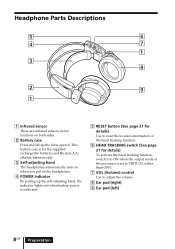
This battery case is for details) To activate the head tracking function, switch it . Headphone Parts Descriptions 5 6 4 7 1 3 8 2 9 1 1 Infrared sensor There are infrared sensors in two locations on the headphones. 4 POWER indicator By pulling up the self-adjusting band, the indicator lights red when battery power ... TRACKING switch (See page 21 for the supplied rechargeable batteries and R6 (size AA) alkaline batteries only. 3 Self-adjusting band The headphones automatically turn on when you put on both sides. 2 Battery case Press and lift up the lid to adjust the volume. 8 ...
This battery case is for details) To activate the head tracking function, switch it . Headphone Parts Descriptions 5 6 4 7 1 3 8 2 9 1 1 Infrared sensor There are infrared sensors in two locations on the headphones. 4 POWER indicator By pulling up the self-adjusting band, the indicator lights red when battery power ... TRACKING switch (See page 21 for the supplied rechargeable batteries and R6 (size AA) alkaline batteries only. 3 Self-adjusting band The headphones automatically turn on when you put on both sides. 2 Battery case Press and lift up the lid to adjust the volume. 8 ...
Operating Instructions
Page 28
... extremely hightemperature location - Replace them when they are replaceable. Dusty location - To replace the ear pads, consult your nearest Sony dealer. • When taking the system to a Sony dealer, be kept at a level where you are not going to use solvents such as thinner, benzene or alcohol as these...volume when using in any of the system. On power sources and placement • If you can respond when called while listening to strong shocks of any parts of the following locations. - There is too high, the sound leaks outside the headphones. On ear pads The ear pads are...
... extremely hightemperature location - Replace them when they are replaceable. Dusty location - To replace the ear pads, consult your nearest Sony dealer. • When taking the system to a Sony dealer, be kept at a level where you are not going to use solvents such as thinner, benzene or alcohol as these...volume when using in any of the system. On power sources and placement • If you can respond when called while listening to strong shocks of any parts of the following locations. - There is too high, the sound leaks outside the headphones. On ear pads The ear pads are...


