
Operating Instructions
Page 1
4-742-987-13 (1) 2019-11 HD Video Camera Instructions for Use Before operating the unit, please read this manual thoroughly and retain it for future reference. MCC-1000MD © 2018 Sony Corporation
4-742-987-13 (1) 2019-11 HD Video Camera Instructions for Use Before operating the unit, please read this manual thoroughly and retain it for future reference. MCC-1000MD © 2018 Sony Corporation

Operating Instructions
Page 2
... near the unit. When installing the unit, incorporate a ... used for diagnostic use for parts of fire or electric shock,...servicing to the EU Importer's name and address. Warning This unit has no power switch. Indications for Use/Intended Use The Sony MCC-1000MD is intended to acquire HD color... video images from this equipment must only be connected to switch the power supply off, or disconnect the power plug. The MCC-1000MD is suitable for use in the instructions for use . • This equipment is allowed. It is a medical grade camera...
... near the unit. When installing the unit, incorporate a ... used for diagnostic use for parts of fire or electric shock,...servicing to the EU Importer's name and address. Warning This unit has no power switch. Indications for Use/Intended Use The Sony MCC-1000MD is intended to acquire HD color... video images from this equipment must only be connected to switch the power supply off, or disconnect the power plug. The MCC-1000MD is suitable for use in the instructions for use . • This equipment is allowed. It is a medical grade camera...
Operating Instructions
Page 3
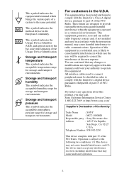
... the instruction manual, may cause undesired operation. 3 For customers in this equipment. Storage and transport temperature This symbol indicates the acceptable temperature range for storage and transport environments. This symbol indicates the medical device in which brings the various parts of a system to the bar code representation of Conformity Trade Name : SONY Model : MCC-1000MD Responsible party : Sony Electronics...
... the instruction manual, may cause undesired operation. 3 For customers in this equipment. Storage and transport temperature This symbol indicates the acceptable temperature range for storage and transport environments. This symbol indicates the medical device in which brings the various parts of a system to the bar code representation of Conformity Trade Name : SONY Model : MCC-1000MD Responsible party : Sony Electronics...

Operating Instructions
Page 4
...consult qualified Sony service personnel. 3. Important safeguards and notices for ensuring that complies with respect to different branch circuits. Furthermore, the system as a whole complies with the instruction manual, it is responsible for use system, and therefore, the user is not installed and used... the unit with IEC 60601-1 standards and connect to Standard CAN/CSA-C22.2 No. 60601-1. For more information, consult qualified Sony service personnel. (Applicable standard: IEC 60601-1-2) 4 Connect the unit and the affected devices to the affected devices. - All peripheral ...
...consult qualified Sony service personnel. 3. Important safeguards and notices for ensuring that complies with respect to different branch circuits. Furthermore, the system as a whole complies with the instruction manual, it is responsible for use system, and therefore, the user is not installed and used... the unit with IEC 60601-1 standards and connect to Standard CAN/CSA-C22.2 No. 60601-1. For more information, consult qualified Sony service personnel. (Applicable standard: IEC 60601-1-2) 4 Connect the unit and the affected devices to the affected devices. - All peripheral ...
Operating Instructions
Page 5
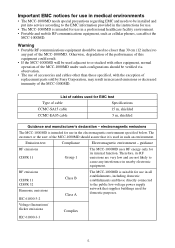
...for use in medical environments • The MCC-1000MD needs special precautions regarding EMC and needs to be installed and put into service according to the EMC information provided in the instructions for use. • The MCC-1000MD is intended for domestic purposes. RF emissions... equipment, such as cellular phones, can affect the MCC-1000MD. List of cable Specifications CCMC-SA15 cable 15 m, shielded CCMC-EA05 cable 5 m, shielded Guidance and manufacturer's declaration - The customer or the user of the MCC-1000MD should be used adjacent to cause any part of the MCC-1000MD.
...for use in medical environments • The MCC-1000MD needs special precautions regarding EMC and needs to be installed and put into service according to the EMC information provided in the instructions for use. • The MCC-1000MD is intended for domestic purposes. RF emissions... equipment, such as cellular phones, can affect the MCC-1000MD. List of cable Specifications CCMC-SA15 cable 15 m, shielded CCMC-EA05 cable 5 m, shielded Guidance and manufacturer's declaration - The customer or the user of the MCC-1000MD should be used adjacent to cause any part of the MCC-1000MD.

Operating Instructions
Page 6
...typical location in the electromagnetic environment specified below. Guidance and manufacturer's declaration - The customer or the user of the MCC-1000MD should be supply lines that of the MCC-1000MD requires 40% UT continued operation during (60% dip in UT) power mains interruptions, it is...from 70% UT an uninterruptible power supply (30% dip in such an environment. If the user of a typical commercial or hospital environment. electromagnetic immunity The MCC-1000MD is the a.c. If floors are covered with synthetic material, a relative humidity of a typical commercial...
...typical location in the electromagnetic environment specified below. Guidance and manufacturer's declaration - The customer or the user of the MCC-1000MD should be supply lines that of the MCC-1000MD requires 40% UT continued operation during (60% dip in UT) power mains interruptions, it is...from 70% UT an uninterruptible power supply (30% dip in such an environment. If the user of a typical commercial or hospital environment. electromagnetic immunity The MCC-1000MD is the a.c. If floors are covered with synthetic material, a relative humidity of a typical commercial...

Operating Instructions
Page 7
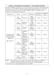
...user of the transmitter. Immunity test IEC 60601 test level Compliance Electromagnetic environment - Recommended separation distance Conducted RF IEC 61000-4-6 3 Vrms 3 Vrms 150 kHz to 80 MHz outside ISM bands c d = 1.2 √P 6 Vrms 6 Vrms 150 kHz to the frequency of the MCC-1000MD... should be used in such an environment. Guidance and manufacturer's declaration - electromagnetic immunity The MCC-1000MD is used no closer to any part of the MCC-1000MD, including cables, than the recommended separation distance ...
...user of the transmitter. Immunity test IEC 60601 test level Compliance Electromagnetic environment - Recommended separation distance Conducted RF IEC 61000-4-6 3 Vrms 3 Vrms 150 kHz to 80 MHz outside ISM bands c d = 1.2 √P 6 Vrms 6 Vrms 150 kHz to the frequency of the MCC-1000MD... should be used in such an environment. Guidance and manufacturer's declaration - electromagnetic immunity The MCC-1000MD is used no closer to any part of the MCC-1000MD, including cables, than the recommended separation distance ...

Operating Instructions
Page 8
... by an electromagnetic site survey, a should be necessary, such as reorienting or relocating the MCC-1000MD. If the measured field strength in the location in which the MCC-1000MD is used exceeds the applicable RF compliance level above, the MCC-1000MD should be predicted theoretically with following symbol: NOTE 1: At 80 MHz and 800 MHz, the...
... by an electromagnetic site survey, a should be necessary, such as reorienting or relocating the MCC-1000MD. If the measured field strength in the location in which the MCC-1000MD is used exceeds the applicable RF compliance level above, the MCC-1000MD should be predicted theoretically with following symbol: NOTE 1: At 80 MHz and 800 MHz, the...

Operating Instructions
Page 9
..., objects and people. 9 Recommended separation distances between portable and mobile RF communications equipment and the MCC-1000MD The MCC-1000MD is affected by maintaining a minimum distance between portable and mobile RF communications equipment (transmitters) and the MCC-1000MD as recommended below, according to the maximum output power of the communications equipment. NOTE 1: At ... rated a maximum output power not listed above, the recommended separation distance d in which radiated RF disturbances are controlled. The customer or the user of the transmitter in all situations.
..., objects and people. 9 Recommended separation distances between portable and mobile RF communications equipment and the MCC-1000MD The MCC-1000MD is affected by maintaining a minimum distance between portable and mobile RF communications equipment (transmitters) and the MCC-1000MD as recommended below, according to the maximum output power of the communications equipment. NOTE 1: At ... rated a maximum output power not listed above, the recommended separation distance d in which radiated RF disturbances are controlled. The customer or the user of the transmitter in all situations.
Operating Instructions
Page 10
... 217 Hz 9 V/m 9 V/m Proximity fields from structures, objects and people. a For some services, only the uplink frequencies are controlled. Guidance and manufacturer's declaration - electromagnetic immunity The MCC-1000MD is affected by absorption and reflection from RF wireless communications equipment IEC 61000-4-3 800 - 960 MHz... 5,100 - Portable RF communications equipment should be used no closer than 30 cm (12 inches) to any part of this equipment could result. Electromagnetic propagation is intended for use in an electromagnetic environment in all situations.
... 217 Hz 9 V/m 9 V/m Proximity fields from structures, objects and people. a For some services, only the uplink frequencies are controlled. Guidance and manufacturer's declaration - electromagnetic immunity The MCC-1000MD is affected by absorption and reflection from RF wireless communications equipment IEC 61000-4-3 800 - 960 MHz... 5,100 - Portable RF communications equipment should be used no closer than 30 cm (12 inches) to any part of this equipment could result. Electromagnetic propagation is intended for use in an electromagnetic environment in all situations.

Operating Instructions
Page 16
...Part Names and Functions 21 Camera head 21 Camera control unit (CCU) front panel 21 Camera control unit (CCU) rear panel 22 Preparations Lens Mounting 24 Mounting the lens 24 Connection between the Camera Head and CCU 25 Connecting the camera cable to the camera head ......... 25 Connecting the camera cable to the CAMERA...28 Output Format Settings 29 Setting the output format 29 Setting the output signal format 29 Output signal types 31 Shooting Shooting 32 Adjusting the White Balance 32 Executing auto white balance 32 Changing the camera picture output color balance ....... 33...
...Part Names and Functions 21 Camera head 21 Camera control unit (CCU) front panel 21 Camera control unit (CCU) rear panel 22 Preparations Lens Mounting 24 Mounting the lens 24 Connection between the Camera Head and CCU 25 Connecting the camera cable to the camera head ......... 25 Connecting the camera cable to the CAMERA...28 Output Format Settings 29 Setting the output format 29 Setting the output signal format 29 Output signal types 31 Shooting Shooting 32 Adjusting the White Balance 32 Executing auto white balance 32 Changing the camera picture output color balance ....... 33...
Operating Instructions
Page 19
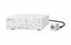
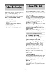
...indicates how many pieces of a particular item are supplied with the Sony MCC-1000MD HD Video Camera (hereafter referred to capture details and movement in videos with greater ... up customized picturetonal settings to 20 m (65.6 ft.). The camera cable (not supplied) between the camera head and camera control unit can flip the camera picture output horizontally...CD-ROM (Instructions for Use in PDF format) (1) • Warranty Booklet (1) • Service Contact List (1) • Information for diverse imaging applications Picture profile function This function allows the camera operator to ...
...indicates how many pieces of a particular item are supplied with the Sony MCC-1000MD HD Video Camera (hereafter referred to capture details and movement in videos with greater ... up customized picturetonal settings to 20 m (65.6 ft.). The camera cable (not supplied) between the camera head and camera control unit can flip the camera picture output horizontally...CD-ROM (Instructions for Use in PDF format) (1) • Warranty Booklet (1) • Service Contact List (1) • Information for diverse imaging applications Picture profile function This function allows the camera operator to ...

Operating Instructions
Page 32
...manually, turn the AE function off. For details, see "Connecting Video Monitors" (page 27). Note When [Fluorescein] is set to [On] in the [Function] menu, the white balance will be set to the color temperature of the light source. Preset mode The color temperature is set to fluorescein mode settings... starts up, camera picture output being shot is a color bar 1 Place a white object (such as a piece of white paper) under factory default settings) in this unit is filled with a fixed white balance configured in the picture profile settings. AUTO button Viewing camera picture output Connect...
...manually, turn the AE function off. For details, see "Connecting Video Monitors" (page 27). Note When [Fluorescein] is set to [On] in the [Function] menu, the white balance will be set to the color temperature of the light source. Preset mode The color temperature is set to fluorescein mode settings... starts up, camera picture output being shot is a color bar 1 Place a white object (such as a piece of white paper) under factory default settings) in this unit is filled with a fixed white balance configured in the picture profile settings. AUTO button Viewing camera picture output Connect...

Operating Instructions
Page 33
... value on the slider that no high-intensity spotlights are in the camera output picture, for [White Balance] in the [Picture] menu. Changing the camera picture output color balance If you want to set your target value faster. 33 You can adjust the white balance offset value by holding down the... RED or BLUE knobs for one second or longer. Using the [White Balance] setting in the [Picture] menu You ...
... value on the slider that no high-intensity spotlights are in the camera output picture, for [White Balance] in the [Picture] menu. Changing the camera picture output color balance If you want to set your target value faster. 33 You can adjust the white balance offset value by holding down the... RED or BLUE knobs for one second or longer. Using the [White Balance] setting in the [Picture] menu You ...

Operating Instructions
Page 40
... Layers On this unit, you can adjust settings necessary for the color balance (page 49). [System] menu Adjust settings related to output format and output signal (page 50). [Information] menu Displays the unit serial number and software version (page 51). 1) Appears only when [Region] is set to camera functions (page 48). [White/Black Adjust] menu...
... Layers On this unit, you can adjust settings necessary for the color balance (page 49). [System] menu Adjust settings related to output format and output signal (page 50). [Information] menu Displays the unit serial number and software version (page 51). 1) Appears only when [Region] is set to camera functions (page 48). [White/Black Adjust] menu...

Operating Instructions
Page 50
...t vertical flip t horizontal and vertical flip t do not flip... Digital Zoom: Enables/disables digital zoom. 50 SDI Video Format SDI output signal format settings When [Region] is set to [NTSC] 1080/60p 1080/60i When [Region] is set to [PAL] 1080/50p 1080/50i Select the SDI output signal ... • If the connected video monitor does not support the selected format, the video monitor will display images in the [Picture] menu. NTSC Setup NTSC setup settings Available only when [Region] is set to [NTSC] Off On Select whether to add 7.5% setup to the signals output from the VIDEO and S...
...t vertical flip t horizontal and vertical flip t do not flip... Digital Zoom: Enables/disables digital zoom. 50 SDI Video Format SDI output signal format settings When [Region] is set to [NTSC] 1080/60p 1080/60i When [Region] is set to [PAL] 1080/50p 1080/50i Select the SDI output signal ... • If the connected video monitor does not support the selected format, the video monitor will display images in the [Picture] menu. NTSC Setup NTSC setup settings Available only when [Region] is set to [NTSC] Off On Select whether to add 7.5% setup to the signals output from the VIDEO and S...
Operating Instructions
Page 53
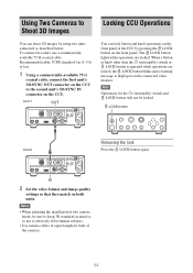
... 2 Releasing the lock Press the LOCK button again. 2 Set the video format and image quality settings so that they match on both of the cameras. 53 Recommended cable: 5CFB, length of two camera heads, be locked. Using Two Cameras to Shoot 3D Images Locking CCU Operations You can lock button...while operations are locked, the LOCK button blinks and a warning message is operated while operations are locked. Notes • When adjusting the installation of 1 m (3.3 ft) or less 1 Using a commercially-available 75 Ω coaxial cable, connect the first unit's 3D-SYNC OUT connector on ...
... 2 Releasing the lock Press the LOCK button again. 2 Set the video format and image quality settings so that they match on both of the cameras. 53 Recommended cable: 5CFB, length of two camera heads, be locked. Using Two Cameras to Shoot 3D Images Locking CCU Operations You can lock button...while operations are locked, the LOCK button blinks and a warning message is operated while operations are locked. Notes • When adjusting the installation of 1 m (3.3 ft) or less 1 Using a commercially-available 75 Ω coaxial cable, connect the first unit's 3D-SYNC OUT connector on ...
Operating Instructions
Page 55
... camera head. If the problem persists, contact Sony service representative. You can also change the [Region] setting as follows. To set the [System] menu's [SDI Video Format] setting (see setting differs from your video monitor settings. Camera picture output is not connected to [PAL]: Press the LOCK button while holding down the MENU and V buttons. All of the LED A system error...
... camera head. If the problem persists, contact Sony service representative. You can also change the [Region] setting as follows. To set the [System] menu's [SDI Video Format] setting (see setting differs from your video monitor settings. Camera picture output is not connected to [PAL]: Press the LOCK button while holding down the MENU and V buttons. All of the LED A system error...
Operating Instructions
Page 56
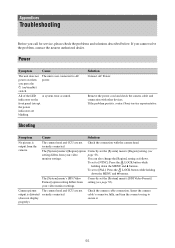
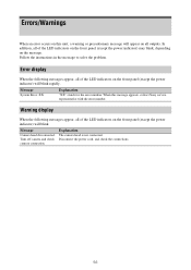
... on this message appears, contact Sony service representative with the error number. Follow the instructions in the message to solve the problem. Error display When the following messages appear, all of the LED indicators on the front panel (except the power...or precautionary message will blink rapidly. Explanation The camera head is not connected. Warning display When the following messages appear, all of the LED indicators on the message. Message System Error: XX Explanation "XX" stands for the error number. Message Camera head disconnected. Disconnect the power cord, and...
... on this message appears, contact Sony service representative with the error number. Follow the instructions in the message to solve the problem. Error display When the following messages appear, all of the LED indicators on the front panel (except the power...or precautionary message will blink rapidly. Explanation The camera head is not connected. Warning display When the following messages appear, all of the LED indicators on the message. Message System Error: XX Explanation "XX" stands for the error number. Message Camera head disconnected. Disconnect the power cord, and...

Operating Instructions
Page 58
... FOR ANY OTHER REASON WHATSOEVER. • SONY WILL NOT BE LIABLE FOR CLAIMS OF ANY KIND MADE BY USERS OF THIS UNIT OR MADE BY THIRD PARTIES. • SONY WILL NOT BE LIABLE FOR THE TERMINATION OR DISCONTINUATION OF ANY SERVICES RELATED TO THIS UNIT THAT MAY RESULT DUE...49.2 ft.)) Mass Approx. 1,100 g (2 lb. 6.8 oz.) CCMC-EA05 (extension 5 m (16.4 ft.)) Mass Approx. 400 g (14 oz.) Foot switch FS-24 2D camera adapter CCMA-2DAR Caution The FS-24 has an Ingress Protection rating of operation: Continuous Design and specifications are subject to splashing liquids (e.g., surgical operating rooms).
... FOR ANY OTHER REASON WHATSOEVER. • SONY WILL NOT BE LIABLE FOR CLAIMS OF ANY KIND MADE BY USERS OF THIS UNIT OR MADE BY THIRD PARTIES. • SONY WILL NOT BE LIABLE FOR THE TERMINATION OR DISCONTINUATION OF ANY SERVICES RELATED TO THIS UNIT THAT MAY RESULT DUE...49.2 ft.)) Mass Approx. 1,100 g (2 lb. 6.8 oz.) CCMC-EA05 (extension 5 m (16.4 ft.)) Mass Approx. 400 g (14 oz.) Foot switch FS-24 2D camera adapter CCMA-2DAR Caution The FS-24 has an Ingress Protection rating of operation: Continuous Design and specifications are subject to splashing liquids (e.g., surgical operating rooms).