Operating Instructions
Page 37
If you have any questions or problems concerning your unit, please consult your unit for service or repair, take note of necessary repair. Malfunction may be deleted depending on the type of important preset settings. Precautions and maintenance • Do not drop or apply excessive force to the unit. Additional information 37GB They may occur as a result. Service and repair When taking your nearest Sony dealer.
If you have any questions or problems concerning your unit, please consult your unit for service or repair, take note of necessary repair. Malfunction may be deleted depending on the type of important preset settings. Precautions and maintenance • Do not drop or apply excessive force to the unit. Additional information 37GB They may occur as a result. Service and repair When taking your nearest Sony dealer.
Operating Instructions
Page 38
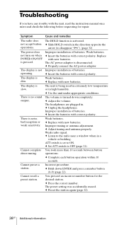
... volume is set to OFF (page 21). c Set ATT switch to ON. Incorrect procedure. You pressed an incorrect number button for repair. c Insert the batteries with correct polarity. c Adjust tuning and antenna properly. c Listen to disappear "-"). (page 32) Improper installation... polarity. The headphones are plugged in the direction opposite the arrow (to the radio near a window when in high humidity. c Unplug the headphones. Weak batteries. c Replace with new batteries. Weak radio signal. ATT switch is turned down ENTER and press a number button (0-9) (...
... volume is set to OFF (page 21). c Set ATT switch to ON. Incorrect procedure. You pressed an incorrect number button for repair. c Insert the batteries with correct polarity. c Adjust tuning and antenna properly. c Listen to disappear "-"). (page 32) Improper installation... polarity. The headphones are plugged in the direction opposite the arrow (to the radio near a window when in high humidity. c Unplug the headphones. Weak batteries. c Replace with new batteries. Weak radio signal. ATT switch is turned down ENTER and press a number button (0-9) (...
Service Manual
Page 12
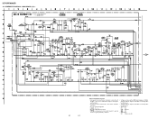
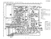
... for electrolytics and tantalums. • All resistors are in µF unless otherwise noted. pF: µµF 50 WV or less are not indicated except for repair. • Voltages and waveforms are taken with respect to normal production tolerances. • Signal path. Voltage variations may be noted due to normal production tolerances... no-signal (detuned) conditions. • Voltages are dc with a VOM (Input impedance 10 MΩ). F : FM L : MW/LW h : SW • Abbreviation CH : Chinese model SCHEMATIC DIAGRAM - ICF-SW7600GR 4-4.
... for electrolytics and tantalums. • All resistors are in µF unless otherwise noted. pF: µµF 50 WV or less are not indicated except for repair. • Voltages and waveforms are taken with respect to normal production tolerances. • Signal path. Voltage variations may be noted due to normal production tolerances... no-signal (detuned) conditions. • Voltages are dc with a VOM (Input impedance 10 MΩ). F : FM L : MW/LW h : SW • Abbreviation CH : Chinese model SCHEMATIC DIAGRAM - ICF-SW7600GR 4-4.
Service Manual
Page 13
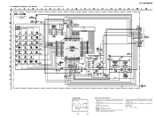
... variations may be noted due to normal production tolerances. • Voltage variations may be noted due to page 16 for repair. • Voltages and waveforms are dc with a VOM (Input impedance 10 MΩ). pF: µµF 50 ... less unless otherwise specified. • ¢ : internal component. • C : panel designation. • A : B+ Line. • H : adjustment for IC Block Diagrams. ICF-SW7600GR IC B/D 1 2 IC B/D IC B/D IC B/D Note on Schematic Diagram: • All capacitors are taken with respect to ground under no-signal (detuned) conditions. • Voltages are...
... variations may be noted due to normal production tolerances. • Voltage variations may be noted due to page 16 for repair. • Voltages and waveforms are dc with a VOM (Input impedance 10 MΩ). pF: µµF 50 ... less unless otherwise specified. • ¢ : internal component. • C : panel designation. • A : B+ Line. • H : adjustment for IC Block Diagrams. ICF-SW7600GR IC B/D 1 2 IC B/D IC B/D IC B/D Note on Schematic Diagram: • All capacitors are taken with respect to ground under no-signal (detuned) conditions. • Voltages are...
Service Manual
Page 15
... WV or less are not indicated except for electrolytics and tantalums. • All resistors are taken with a VOM (Input impedance 10 MΩ). ICF-SW7600GR 1 • WAVEFORM 1 IC302 wf 13.3 µs 15 1.8 Vp-p 15 Note on Schematic Diagram: • All capacitors are dc with respect...due to ground under no-signal (detuned) conditions. • Voltages are in µF unless otherwise noted. KEY BOARD - • Refer to page 16 for repair. • Voltages and waveforms are in Ω and 1/4 W or less unless otherwise specified. • C : panel designation. • A : B+ Line...
... WV or less are not indicated except for electrolytics and tantalums. • All resistors are taken with a VOM (Input impedance 10 MΩ). ICF-SW7600GR 1 • WAVEFORM 1 IC302 wf 13.3 µs 15 1.8 Vp-p 15 Note on Schematic Diagram: • All capacitors are dc with respect...due to ground under no-signal (detuned) conditions. • Voltages are in µF unless otherwise noted. KEY BOARD - • Refer to page 16 for repair. • Voltages and waveforms are in Ω and 1/4 W or less unless otherwise specified. • C : panel designation. • A : B+ Line...
