Operating Instructions
Page 2
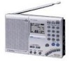
... Changing the settings to a station by turning the equipment off the radio so that to which can be able to listen to suit your Sony dealer regarding this unit is factory-set to correct the interference by ... • Five types tuning methods to the radio (see page 15). Memory scan tuning for the sleep timer to activate from that you call your needs - ICF-SW7600GR Serial No Warning To prevent fire or shock hazard... station of your choice at the rear of this product. Owner's record The model and serial numbers are located at the time of the following measures: -
... Changing the settings to a station by turning the equipment off the radio so that to which can be able to listen to suit your Sony dealer regarding this unit is factory-set to correct the interference by ... • Five types tuning methods to the radio (see page 15). Memory scan tuning for the sleep timer to activate from that you call your needs - ICF-SW7600GR Serial No Warning To prevent fire or shock hazard... station of your choice at the rear of this product. Owner's record The model and serial numbers are located at the time of the following measures: -
Service Manual
Page 12
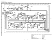
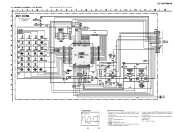
...not indicated except for electrolytics and tantalums. • All resistors are in µF unless otherwise noted. Voltage variations may be noted due to normal production tolerances. • Voltage variations may be noted due to ground under no-signal (detuned) conditions. • Voltages are in Ω and 1/4... MΩ). SCHEMATIC DIAGRAM - MAIN BOARD (1/2) - 12 12 Note on Schematic Diagram: • All capacitors are taken with respect to normal production tolerances. • Signal path. ICF-SW7600GR 4-4. F : FM L : MW/LW h : SW • Abbreviation CH : Chinese model
...not indicated except for electrolytics and tantalums. • All resistors are in µF unless otherwise noted. Voltage variations may be noted due to normal production tolerances. • Voltage variations may be noted due to ground under no-signal (detuned) conditions. • Voltages are in Ω and 1/4... MΩ). SCHEMATIC DIAGRAM - MAIN BOARD (1/2) - 12 12 Note on Schematic Diagram: • All capacitors are taken with respect to normal production tolerances. • Signal path. ICF-SW7600GR 4-4. F : FM L : MW/LW h : SW • Abbreviation CH : Chinese model
Service Manual
Page 13
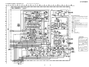
... normal production tolerances. • Signal path. SCHEMATIC DIAGRAM - pF: µµF 50 WV or less are not indicated except for electrolytics and tantalums. • All resistors are in Ω and 1/4 W or less unless otherwise specified. • ¢ : internal component. • C : panel designation. • A : B+ Line. • H : adjustment for IC Block Diagrams. ICF-SW7600GR IC...
... normal production tolerances. • Signal path. SCHEMATIC DIAGRAM - pF: µµF 50 WV or less are not indicated except for electrolytics and tantalums. • All resistors are in Ω and 1/4 W or less unless otherwise specified. • ¢ : internal component. • C : panel designation. • A : B+ Line. • H : adjustment for IC Block Diagrams. ICF-SW7600GR IC...
Service Manual
Page 15
... respect to page 16 for IC Pin Function. Voltage variations may be noted due to normal production tolerances. • Voltage variations may be noted due to normal production tolerances. • Abbreviation CH : Chinese model SCHEMATIC DIAGRAM - ICF-SW7600GR 1 • WAVEFORM 1 IC302 wf 13.3 µs 15 1.8 Vp-p 15 Note on Schematic Diagram: • All capacitors...
... respect to page 16 for IC Pin Function. Voltage variations may be noted due to normal production tolerances. • Voltage variations may be noted due to normal production tolerances. • Abbreviation CH : Chinese model SCHEMATIC DIAGRAM - ICF-SW7600GR 1 • WAVEFORM 1 IC302 wf 13.3 µs 15 1.8 Vp-p 15 Note on Schematic Diagram: • All capacitors...

