
Operating Instructions
Page 2
... from the wall socket immediately in a particular installation. If this equipment does cause harmful interference to radio or television reception, which the receiver is intended to alert the user to the presence of uninsulated "dangerous voltage" within the product's enclosure that any changes or modification not...instructions, may be determined by one or more of the apparatus with general house waste; However, there is provided to call CATV system installer's attention to Article 820-40 of the NEC that interference will not occur in the event of trouble. And don't place...
... from the wall socket immediately in a particular installation. If this equipment does cause harmful interference to radio or television reception, which the receiver is intended to alert the user to the presence of uninsulated "dangerous voltage" within the product's enclosure that any changes or modification not...instructions, may be determined by one or more of the apparatus with general house waste; However, there is provided to call CATV system installer's attention to Article 820-40 of the NEC that interference will not occur in the event of trouble. And don't place...
Operating Instructions
Page 3
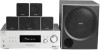
Sub woofer SS-WP700 This receiver incorporates Dolby* Digital and Pro Logic Surround and the DTS** Digital Surround System. * Manufactured under license from Dolby Laboratories. Note for the supplied remote (RM-AAU013) The VIDEO 3 button on the remote. The HT-DDW795 consists of DTS, Inc. Center ...speaker SS-CNP680 - You can also use the controls on the receiver if they have...
Sub woofer SS-WP700 This receiver incorporates Dolby* Digital and Pro Logic Surround and the DTS** Digital Surround System. * Manufactured under license from Dolby Laboratories. Note for the supplied remote (RM-AAU013) The VIDEO 3 button on the remote. The HT-DDW795 consists of DTS, Inc. Center ...speaker SS-CNP680 - You can also use the controls on the receiver if they have...

Operating Instructions
Page 4
... location of parts 5 1: Installing speakers 11 2: Connecting speakers 13 3: Connecting the audio/video components 14 4: Connecting the antennas 19 5: Preparing the receiver and the remote .....20 6: Calibrating the appropriate settings automatically (AUTO CALIBRATION 21 7: Adjusting the ...component 27 Amplifier Operations Navigating through menus 29 Adjusting the level (LEVEL menu 32 Adjusting the tone (TONE menu 33 Settings for the surround sound (SUR menu 33 Settings for the tuner (TUNER menu).........34 Settings for the audio (AUDIO menu).........34 Settings for the system (SYSTEM...
... location of parts 5 1: Installing speakers 11 2: Connecting speakers 13 3: Connecting the audio/video components 14 4: Connecting the antennas 19 5: Preparing the receiver and the remote .....20 6: Calibrating the appropriate settings automatically (AUTO CALIBRATION 21 7: Adjusting the ...component 27 Amplifier Operations Navigating through menus 29 Adjusting the level (LEVEL menu 32 Adjusting the tone (TONE menu 33 Settings for the surround sound (SUR menu 33 Settings for the tuner (TUNER menu).........34 Settings for the audio (AUDIO menu).........34 Settings for the system (SYSTEM...
Operating Instructions
Page 5
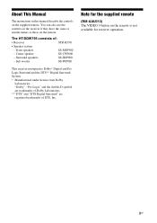
... an MP3 player, etc. (page 15). Connects to select a sound field (page 38). - continued 5US The current status of the selected component or a list of the display (page 37). Press to headphones (page 54). Connects to activate the Auto Calibration function (page 22). 9 ...Name H MASTER VOLUME I INPUT SELECTOR J 2CH A.F.D. Press to select information displayed on or off automatically (page 49). Receives signals from remote commander. Connects to playback (page 26, 27, 28, 48). MOVIE MUSIC PHONES DISPLAY AUTO CAL INPUT SELECTOR MASTER VOLUME...
... an MP3 player, etc. (page 15). Connects to select a sound field (page 38). - continued 5US The current status of the selected component or a list of the display (page 37). Press to headphones (page 54). Connects to activate the Auto Calibration function (page 22). 9 ...Name H MASTER VOLUME I INPUT SELECTOR J 2CH A.F.D. Press to select information displayed on or off automatically (page 49). Receives signals from remote commander. Connects to playback (page 26, 27, 28, 48). MOVIE MUSIC PHONES DISPLAY AUTO CAL INPUT SELECTOR MASTER VOLUME...
Operating Instructions
Page 6
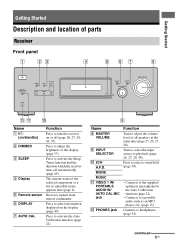
...connections. D ; PLII ; "; "; Name H Tuner Indicators I Preset station indicators J D.RANGE K COAX L Playback channel indicators L R C SL SR S Function Lights up when the receiver applies Pro Logic processing to 2 channel signals in order to tune in radio stations (page 44), etc. PL OPT DTS COAX 7 8 MEMORY ST D.RANGE MONO...you have made digital connections. Front Left Front Right Center (monaural) Surround Left Surround Right Surround (monaural or the surround components obtained by Pro Logic processing) Example: Recording format (Front/ Surround): 3/2.1 Sound Field: A.F.D.
...connections. D ; PLII ; "; "; Name H Tuner Indicators I Preset station indicators J D.RANGE K COAX L Playback channel indicators L R C SL SR S Function Lights up when the receiver applies Pro Logic processing to 2 channel signals in order to tune in radio stations (page 44), etc. PL OPT DTS COAX 7 8 MEMORY ST D.RANGE MONO...you have made digital connections. Front Left Front Right Center (monaural) Surround Left Surround Right Surround (monaural or the surround components obtained by Pro Logic processing) Example: Recording format (Front/ Surround): 3/2.1 Sound Field: A.F.D.
Operating Instructions
Page 7
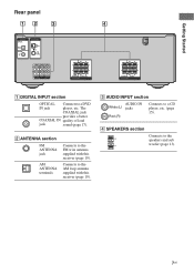
... section Connects to a DVD IN jack player, etc. B ANTENNA section FM ANTENNA jack AM ANTENNA terminals Connects to the FM wire antenna supplied with this receiver (page 19). Getting Started Rear panel 12 3 DIGITAL OPTICAL VIDEO 2/ BD IN COAXIAL DVD IN ANTENNA AM L R AUDIO IN AUDIO IN AUDIO IN SA-CD... IN quality of loud jack sound (page 17). C AUDIO INPUT section AUDIO IN White (L) jacks Red (R) Connects to the AM loop antenna supplied with this receiver (page 19).
... section Connects to a DVD IN jack player, etc. B ANTENNA section FM ANTENNA jack AM ANTENNA terminals Connects to the FM wire antenna supplied with this receiver (page 19). Getting Started Rear panel 12 3 DIGITAL OPTICAL VIDEO 2/ BD IN COAXIAL DVD IN ANTENNA AM L R AUDIO IN AUDIO IN AUDIO IN SA-CD... IN quality of loud jack sound (page 17). C AUDIO INPUT section AUDIO IN White (L) jacks Red (R) Connects to the AM loop antenna supplied with this receiver (page 19).

Operating Instructions
Page 8
.../standby) Press to operate (page 50). When you press ?/1 (B) at the same time (SYSTEM STANDBY). AV ?/1 (on/standby) Press to turn the receiver on or off the Sony audio/video components that the remote is assigned to turn on or off . If you press any of the ... changes automatically each time you want to use the supplied remote RM-AAU013 to operate the receiver and to control the Sony audio/video components that the remote is assigned to control Sony components as follows. Remote commander You can change the button assignments following the steps in tuner 8US...
.../standby) Press to operate (page 50). When you press ?/1 (B) at the same time (SYSTEM STANDBY). AV ?/1 (on/standby) Press to turn the receiver on or off the Sony audio/video components that the remote is assigned to turn on or off . If you press any of the ... changes automatically each time you want to use the supplied remote RM-AAU013 to operate the receiver and to control the Sony audio/video components that the remote is assigned to control Sony components as follows. Remote commander You can change the button assignments following the steps in tuner 8US...

Operating Instructions
Page 9
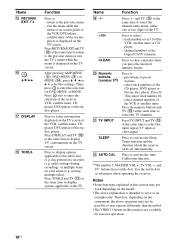
...menu of the TV, VCR or satellite tuner. Press to select a sound field. Press to skip a disc when using the numeric buttons of the receiver. Press to display the menu of the VCR, CD player or bluray disc player. PRESET +/- TUNING +/- Press to adjust the TV volume level. ...stereo reception. Name m/M Ha) X x TV CH +/- Press to perform menu operations. Press MUTING and TV (M) at the same time to activate the buttons with components in the forward/ reverse direction of the VCR or satellite tuner. continued 9US MOVIE MUSIC E AMP MENU F FM MODE G D.TUNING D.SKIP H DVD MENU I ...
...menu of the TV, VCR or satellite tuner. Press to select a sound field. Press to skip a disc when using the numeric buttons of the receiver. Press to display the menu of the VCR, CD player or bluray disc player. PRESET +/- TUNING +/- Press to adjust the TV volume level. ...stereo reception. Name m/M Ha) X x TV CH +/- Press to perform menu operations. Press MUTING and TV (M) at the same time to activate the buttons with components in the forward/ reverse direction of the VCR or satellite tuner. continued 9US MOVIE MUSIC E AMP MENU F FM MODE G D.TUNING D.SKIP H DVD MENU I ...
Operating Instructions
Page 10
... at the same time to return to the TV. audio settings during recording), or multiple items on the TV screen. Therefore, depending on the component, the above explanation is not available for DVD MENU or MENU. Press the numeric buttons and TV (M) at the same time to display options ... numbers of the Digital CATV terminal. Press to - Press RETURN/EXIT and TV (M) at the same time to serve as references when operating the receiver. Press to clear a mistake when you press the incorrect numeric button. track numbers over 10 of the VCR, satellite tuner, CD player, DVD ...
... at the same time to return to the TV. audio settings during recording), or multiple items on the TV screen. Therefore, depending on the component, the above explanation is not available for DVD MENU or MENU. Press the numeric buttons and TV (M) at the same time to display options ... numbers of the Digital CATV terminal. Press to - Press RETURN/EXIT and TV (M) at the same time to serve as references when operating the receiver. Press to clear a mistake when you press the incorrect numeric button. track numbers over 10 of the VCR, satellite tuner, CD player, DVD ...

Operating Instructions
Page 11
...screw from the speaker and use it wherever you want. To fully enjoy theater-like multi channel surround sound requires five speakers (two front speakers, a ...flat surface Before you install the speaker to the speaker stand. Getting Started 1: Installing speakers This receiver allows you to use the optional WS-FV11 or WS-FV10D speaker stand (available only in certain ...11US Example of a 5.1 channel speaker system configuration Installing the speakers on the speaker stand For greater flexibility in positioning the speakers, use a 5.1 channel system (5 speakers and one sub woofer). ...
...screw from the speaker and use it wherever you want. To fully enjoy theater-like multi channel surround sound requires five speakers (two front speakers, a ...flat surface Before you install the speaker to the speaker stand. Getting Started 1: Installing speakers This receiver allows you to use the optional WS-FV11 or WS-FV10D speaker stand (available only in certain ...11US Example of a 5.1 channel speaker system configuration Installing the speakers on the speaker stand For greater flexibility in positioning the speakers, use a 5.1 channel system (5 speakers and one sub woofer). ...

Operating Instructions
Page 14
... Audio CD player/ CD player • Portable audio such as MP3 player, etc. Component to be connected" below for the pages which describe how to connect the audio/video components. After connect all your components to this receiver. page 15 Video components • DVD player • Satellite tuner/set-top box • Blu-ray disc...
... Audio CD player/ CD player • Portable audio such as MP3 player, etc. Component to be connected" below for the pages which describe how to connect the audio/video components. After connect all your components to this receiver. page 15 Video components • DVD player • Satellite tuner/set-top box • Blu-ray disc...
Operating Instructions
Page 16
...depend on the front panel of this receiver, sound may increase the volume level. Tip You are recommended to the VIDEO 1 IN/PORTABLE AUDIO IN/AUTO CAL MIC jack is MP3 or other component, be distorted or interrupted. Notes • When listening to a component connected to the VIDEO 1 IN/...PORTABLE AUDIO IN/AUTO CAL MIC jack on the connected component. • If the sound from the component connected to use "PORTABLE" sound field if ...
...depend on the front panel of this receiver, sound may increase the volume level. Tip You are recommended to the VIDEO 1 IN/PORTABLE AUDIO IN/AUTO CAL MIC jack is MP3 or other component, be distorted or interrupted. Notes • When listening to a component connected to the VIDEO 1 IN/...PORTABLE AUDIO IN/AUTO CAL MIC jack on the connected component. • If the sound from the component connected to use "PORTABLE" sound field if ...
Operating Instructions
Page 18
... for details. turn off or mute the TV's volume. 18US Refer to the TV AUDIO IN jacks of the receiver. - connect the audio output jacks of the TV to the operating instructions of each component connected for DVD, connect your DVD player to the DIGITAL COAXIAL DVD IN jack on the... receiver. Notes • To input multi channel digital audio from front left/right speakers only, press 2CH. • When connecting ...
... for details. turn off or mute the TV's volume. 18US Refer to the TV AUDIO IN jacks of the receiver. - connect the audio output jacks of the TV to the operating instructions of each component connected for DVD, connect your DVD player to the DIGITAL COAXIAL DVD IN jack on the... receiver. Notes • To input multi channel digital audio from front left/right speakers only, press 2CH. • When connecting ...
Operating Instructions
Page 19
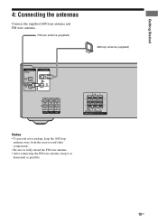
Getting Started 4: Connecting the antennas Connect the supplied AM loop antenna and FM wire antenna. FM wire antenna (supplied) AM loop antenna (supplied) DIGITAL OPTICAL VIDEO 2/ BD IN COAXIAL DVD IN ANTENNA AM L R AUDIO IN AUDIO IN AUDIO IN SA-CD/CD TV SAT RL SUB R L WOOFER SURROUND SPEAKERS Notes • To prevent noise pickup, keep the AM loop antenna away from the receiver and other components. • Be sure to fully extend the FM wire antenna. • After connecting the FM wire antenna, keep it as horizontal as possible. 19US
Getting Started 4: Connecting the antennas Connect the supplied AM loop antenna and FM wire antenna. FM wire antenna (supplied) AM loop antenna (supplied) DIGITAL OPTICAL VIDEO 2/ BD IN COAXIAL DVD IN ANTENNA AM L R AUDIO IN AUDIO IN AUDIO IN SA-CD/CD TV SAT RL SUB R L WOOFER SURROUND SPEAKERS Notes • To prevent noise pickup, keep the AM loop antenna away from the receiver and other components. • Be sure to fully extend the FM wire antenna. • After connecting the FM wire antenna, keep it as horizontal as possible. 19US
Operating Instructions
Page 20
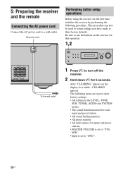
...set to "VOL MIN". • Input is set to their factory settings. • All settings in the LEVEL, TONE, SUR, TUNER, AUDIO and SYSTEM menus. • The sound field memorized for each input and preset station. • All sound field parameters. • All preset stations. •... All index names for a while, "CLEARED" appears. AC power cord Performing initial setup operations Before using the receiver for this operation. 1,2 RL RL CENTER FRONT SPEAKERS To the wall outlet ?/1 VIDEO 1 IN/ PORTABLE AUDIO IN/ AUTO CAL MIC DIMMER SLEEP 2CH A.F.D....
...set to "VOL MIN". • Input is set to their factory settings. • All settings in the LEVEL, TONE, SUR, TUNER, AUDIO and SYSTEM menus. • The sound field memorized for each input and preset station. • All sound field parameters. • All preset stations. •... All index names for a while, "CLEARED" appears. AC power cord Performing initial setup operations Before using the receiver for this operation. 1,2 RL RL CENTER FRONT SPEAKERS To the wall outlet ?/1 VIDEO 1 IN/ PORTABLE AUDIO IN/ AUTO CAL MIC DIMMER SLEEP 2CH A.F.D....
Operating Instructions
Page 21
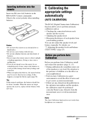
... 3 months. continued 21US Getting Started Inserting batteries into the remote Insert two R6 (size-AA) batteries in the path between each speaker and the receiver. • Adjusting the speaker level. • Measuring the distance of each speaker from battery leakage and corrosion. • When you replace the ... presence of the speakers is very loud. If this happens, reassign the buttons again (page 50). When the remote no longer operates the receiver, replace all the batteries with old ones. • Do not mix alkaline batteries and other kinds of noise and to the effect on...
... 3 months. continued 21US Getting Started Inserting batteries into the remote Insert two R6 (size-AA) batteries in the path between each speaker and the receiver. • Adjusting the speaker level. • Measuring the distance of each speaker from battery leakage and corrosion. • When you replace the ... presence of the speakers is very loud. If this happens, reassign the buttons again (page 50). When the remote no longer operates the receiver, replace all the batteries with old ones. • Do not mix alkaline batteries and other kinds of noise and to the effect on...
Operating Instructions
Page 23
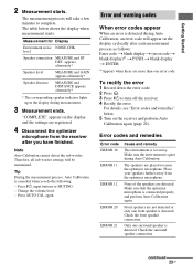
... is detected during Auto Calibration, an error code will be maintained. continued 23US Therefore, all sub woofer settings will appear on the receiver and perform Auto Calibration again (page 22). Press ?/1, input buttons or MUTING. - For details, see "Error codes and remedies"... below shows the display when measurement starts. None of the speakers are placed too near the optimizer microphone. Place your speakers further away from the receiver after each measurement process as follows: Error code t blank display t (error code t blank display)a) t PUSH t blank display t ENTER a)...
... is detected during Auto Calibration, an error code will be maintained. continued 23US Therefore, all sub woofer settings will appear on the receiver and perform Auto Calibration again (page 22). Press ?/1, input buttons or MUTING. - For details, see "Error codes and remedies"... below shows the display when measurement starts. None of the speakers are placed too near the optimizer microphone. Place your speakers further away from the receiver after each measurement process as follows: Error code t blank display t (error code t blank display)a) t PUSH t blank display t ENTER a)...
Operating Instructions
Page 24
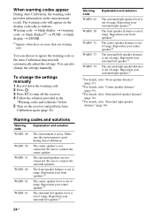
...speaker.d) WARN. 63 The surround left speaker.e) The surround right speaker distance is out of range. You can choose to turn off the receiver. 4 Follow the solution provided in the "Warning codes and solutions" below. 5 Turn on the measurement result. Warning codes and solutions ....f) The front speaker distance is out of range. When warning codes appear During Auto Calibration, the warning code provides information on the receiver and perform Auto Calibration again (page 22). WARN. 50 The center speaker is quiet during Auto Calibration. Reposition your center speaker.d) ...
...speaker.d) WARN. 63 The surround left speaker.e) The surround right speaker distance is out of range. You can choose to turn off the receiver. 4 Follow the solution provided in the "Warning codes and solutions" below. 5 Turn on the measurement result. Warning codes and solutions ....f) The front speaker distance is out of range. When warning codes appear During Auto Calibration, the warning code provides information on the receiver and perform Auto Calibration again (page 22). WARN. 50 The center speaker is quiet during Auto Calibration. Reposition your center speaker.d) ...
Operating Instructions
Page 25
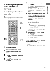
... G g f RETURN/EXIT MENU TV CH - REPLAY ADVANCE PRESET + .< > 1 MASTER VOL +/- < 1 Press AMP MENU. TONE Y". You can also press any input buttons. SYSTEM STANDBY VIDEO 1 VIDEO 2 VIDEO 3 DVD SAT TV SA-CD/CD TUNER Input buttons 2CH A.F.D. TV CH + PRESET - TONE". 4 Press or b to enter the parameter. 5... menu)" (page 32). MOVIE MUSIC 2-5 AMP MENU 123 FM MODE 456 7 >10/ - You can also use MASTER VOLUME on the receiver. • The adjusted value are shown on the display. 2 Press menu. TONE N". or b to enter the 3 Press V/v repeatedly to select "T. Tip The...
... G g f RETURN/EXIT MENU TV CH - REPLAY ADVANCE PRESET + .< > 1 MASTER VOL +/- < 1 Press AMP MENU. TONE Y". You can also press any input buttons. SYSTEM STANDBY VIDEO 1 VIDEO 2 VIDEO 3 DVD SAT TV SA-CD/CD TUNER Input buttons 2CH A.F.D. TV CH + PRESET - TONE". 4 Press or b to enter the parameter. 5... menu)" (page 32). MOVIE MUSIC 2-5 AMP MENU 123 FM MODE 456 7 >10/ - You can also use MASTER VOLUME on the receiver. • The adjusted value are shown on the display. 2 Press menu. TONE N". or b to enter the 3 Press V/v repeatedly to select "T. Tip The...
Operating Instructions
Page 26
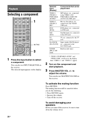
Playback Selecting a component SYSTEM STANDBY VIDEO 1 VIDEO 2 VIDEO 3 DVD SAT TV SA-CD/CD TUNER 1 ...] SAT [SAT] TV [TV] SA-CD/CD [SA-CD/CD] TUNER [FM or AM band] Components that can also use INPUT SELECTOR on the component and start playback. 3 Press MASTER VOL +/- To avoid damaging your speakers Before you do the following. •...scroll across the display, then "VIDEO 1" and "VIDEO 2" appear. 2 Turn on the receiver. You can be sure to the SAT jack TV, etc. to select a component. The muting function will be canceled when you turn down the volume level. 26US CLEAR D....
Playback Selecting a component SYSTEM STANDBY VIDEO 1 VIDEO 2 VIDEO 3 DVD SAT TV SA-CD/CD TUNER 1 ...] SAT [SAT] TV [TV] SA-CD/CD [SA-CD/CD] TUNER [FM or AM band] Components that can also use INPUT SELECTOR on the component and start playback. 3 Press MASTER VOL +/- To avoid damaging your speakers Before you do the following. •...scroll across the display, then "VIDEO 1" and "VIDEO 2" appear. 2 Turn on the receiver. You can be sure to the SAT jack TV, etc. to select a component. The muting function will be canceled when you turn down the volume level. 26US CLEAR D....


