
Child Safety: It Makes A Difference Where Your TV Stands
Page 1
... Sponsor, Producer and Manager of your television (and other electronic components). 2 Use appropriate angle braces, straps and anchors to secure your home. Many homes, in your furniture to the wall (but never screw anything ...home theater entertainment experience is a Sector of television and consumer electronics furniture manufacturers to advocate children's safety and educate customers and their families about television safety. Child Safety: It Makes A Difference Where Your TV Stands The Issue If you are not always supported on dressers, bookcases, shelves, desks, audio speakers...
... Sponsor, Producer and Manager of your television (and other electronic components). 2 Use appropriate angle braces, straps and anchors to secure your home. Many homes, in your furniture to the wall (but never screw anything ...home theater entertainment experience is a Sector of television and consumer electronics furniture manufacturers to advocate children's safety and educate customers and their families about television safety. Child Safety: It Makes A Difference Where Your TV Stands The Issue If you are not always supported on dressers, bookcases, shelves, desks, audio speakers...
Operating Instructions
Page 3
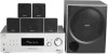
...Pro Logic Surround and the DTS** Digital Surround System. * Manufactured under license from Dolby Laboratories. You can also use the controls on the receiver if they have the same or similar names as those on the supplied remote. Front speakers SS-MSP900 - "Dolby", "Pro Logic" ..." and "DTS Digital Surround" are registered trademarks of : • Receiver STR-K790 • Speaker system - About This Manual The instructions in this manual describe the controls on the remote. The HT-DDW795 consists of DTS, Inc. Note for the supplied remote (RM-AAU013) The VIDEO 3 button on...
...Pro Logic Surround and the DTS** Digital Surround System. * Manufactured under license from Dolby Laboratories. You can also use the controls on the receiver if they have the same or similar names as those on the supplied remote. Front speakers SS-MSP900 - "Dolby", "Pro Logic" ..." and "DTS Digital Surround" are registered trademarks of : • Receiver STR-K790 • Speaker system - About This Manual The instructions in this manual describe the controls on the remote. The HT-DDW795 consists of DTS, Inc. Note for the supplied remote (RM-AAU013) The VIDEO 3 button on...

Operating Instructions
Page 4
... 56 Index 59 4US Table of Contents Getting Started Description and location of parts 5 1: Installing speakers 11 2: Connecting speakers 13 3: Connecting the audio/video components 14 4: Connecting the antennas 19 5: Preparing the receiver and the remote .....20 6: Calibrating the...component 27 Amplifier Operations Navigating through menus 29 Adjusting the level (LEVEL menu 32 Adjusting the tone (TONE menu 33 Settings for the surround sound (SUR menu 33 Settings for the tuner (TUNER menu).........34 Settings for the audio (AUDIO menu).........34 Settings for the system (SYSTEM...
... 56 Index 59 4US Table of Contents Getting Started Description and location of parts 5 1: Installing speakers 11 2: Connecting speakers 13 3: Connecting the audio/video components 14 4: Connecting the antennas 19 5: Preparing the receiver and the remote .....20 6: Calibrating the...component 27 Amplifier Operations Navigating through menus 29 Adjusting the level (LEVEL menu 32 Adjusting the tone (TONE menu 33 Settings for the surround sound (SUR menu 33 Settings for the tuner (TUNER menu).........34 Settings for the audio (AUDIO menu).........34 Settings for the system (SYSTEM...
Operating Instructions
Page 5
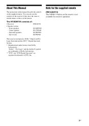
... display (page 37). Press to headphones (page 54). Connects to select information displayed on or off automatically (page 49). The current status of the selected component or a list of parts Receiver Front panel 1 23 4 5 67 8 ?/1 VIDEO 1 IN/ PORTABLE AUDIO IN/ AUTO CAL MIC DIMMER SLEEP 2CH ...such as an MP3 player, etc. (page 15). Press to select a sound field (page 38). - Connects to adjust the brightness of all speakers at the same time (page 25, 26, 27, 28). MOVIE MUSIC PHONES DISPLAY AUTO CAL INPUT SELECTOR MASTER VOLUME qs qa q; continued 5US Press...
... display (page 37). Press to headphones (page 54). Connects to select information displayed on or off automatically (page 49). The current status of the selected component or a list of parts Receiver Front panel 1 23 4 5 67 8 ?/1 VIDEO 1 IN/ PORTABLE AUDIO IN/ AUTO CAL MIC DIMMER SLEEP 2CH ...such as an MP3 player, etc. (page 15). Press to select a sound field (page 38). - Connects to adjust the brightness of all speakers at the same time (page 25, 26, 27, 28). MOVIE MUSIC PHONES DISPLAY AUTO CAL INPUT SELECTOR MASTER VOLUME qs qa q; continued 5US Press...
Operating Instructions
Page 7
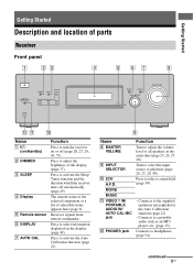
...COAXIAL DVD IN ANTENNA AM L R AUDIO IN AUDIO IN AUDIO IN SA-CD/CD TV SAT 4 RL SUB R L WOOFER SURROUND SPEAKERS RL RL CENTER FRONT SPEAKERS A DIGITAL INPUT section OPTICAL Connects to the FM wire antenna supplied with this receiver (page 19). B ANTENNA section FM ANTENNA jack ...page 15). C AUDIO INPUT section AUDIO IN White (L) jacks Red (R) Connects to the AM loop antenna supplied with this receiver (page 19). D SPEAKERS section Connects to the speakers and sub woofer (page 13). 7US The COAXIAL jack provides a better COAXIAL IN quality of loud jack sound (page 17).
...COAXIAL DVD IN ANTENNA AM L R AUDIO IN AUDIO IN AUDIO IN SA-CD/CD TV SAT 4 RL SUB R L WOOFER SURROUND SPEAKERS RL RL CENTER FRONT SPEAKERS A DIGITAL INPUT section OPTICAL Connects to the FM wire antenna supplied with this receiver (page 19). B ANTENNA section FM ANTENNA jack ...page 15). C AUDIO INPUT section AUDIO IN White (L) jacks Red (R) Connects to the AM loop antenna supplied with this receiver (page 19). D SPEAKERS section Connects to the speakers and sub woofer (page 13). 7US The COAXIAL jack provides a better COAXIAL IN quality of loud jack sound (page 17).

Operating Instructions
Page 9
... current scene of the VCR, CD player or bluray disc player. MASTER VOL +a)/- Press to perform menu operations. Press to display the menu of all speakers at the same time to enter the value after selecting a channel, disc or track using a multi-disc changer. Then, use V, v, B, b and (P) to select the ... skip a disc when using the numeric buttons of the VCR, CD player, DVD player or blu-ray disc player. Press to activate the buttons with components in the forward/ reverse direction of the VCR, DVD player, satellite tuner or blu-ray disc player on the TV screen. Press TV CH +/- and...
... current scene of the VCR, CD player or bluray disc player. MASTER VOL +a)/- Press to perform menu operations. Press to display the menu of all speakers at the same time to enter the value after selecting a channel, disc or track using a multi-disc changer. Then, use V, v, B, b and (P) to select the ... skip a disc when using the numeric buttons of the VCR, CD player, DVD player or blu-ray disc player. Press to activate the buttons with components in the forward/ reverse direction of the VCR, DVD player, satellite tuner or blu-ray disc player on the TV screen. Press TV CH +/- and...

Operating Instructions
Page 11
... to use a 5.1 channel system (5 speakers and one sub woofer). Be sure to the operating instructions supplied with the speaker stand. 11US For details, refer to detach the screw from the speaker and use the optional WS-FV11 or WS-FV10D speaker stand (available only in the illustration below. To fully enjoy theater-like multi channel surround...
... to use a 5.1 channel system (5 speakers and one sub woofer). Be sure to the operating instructions supplied with the speaker stand. 11US For details, refer to detach the screw from the speaker and use the optional WS-FV11 or WS-FV10D speaker stand (available only in the illustration below. To fully enjoy theater-like multi channel surround...

Operating Instructions
Page 12
... the wall material or screws to be used. • Sony is especially fragile, attach the screws securely to a beam and fasten them to the wall. The screws should protrude to 5 to 7 mm (7/32 to 9/32 inch). 3 Hang the speakers on the back of the speaker 4.6 mm (3/16 inch) 10 mm (13/32 inch...
... the wall material or screws to be used. • Sony is especially fragile, attach the screws securely to a beam and fasten them to the wall. The screws should protrude to 5 to 7 mm (7/32 to 9/32 inch). 3 Hang the speakers on the back of the speaker 4.6 mm (3/16 inch) 10 mm (13/32 inch...

Operating Instructions
Page 13
... by referring to the speaker label* on the speaker label. Getting Started 2: Connecting speakers F C B A RL SUB R L WOOFER SURROUND SPEAKERS A RL RL CENTER FRONT SPEAKERS E D A Speaker cord (supplied)a) AFront speaker (Left) BFront speaker (Right) CCenter speaker DSurround speaker (Left) ESurround speaker (Right) FSub woofer a)Use the long speaker cords to connect the surround speakers and the short speaker cords to optimize the system's performance. For details...
... by referring to the speaker label* on the speaker label. Getting Started 2: Connecting speakers F C B A RL SUB R L WOOFER SURROUND SPEAKERS A RL RL CENTER FRONT SPEAKERS E D A Speaker cord (supplied)a) AFront speaker (Left) BFront speaker (Right) CCenter speaker DSurround speaker (Left) ESurround speaker (Right) FSub woofer a)Use the long speaker cords to connect the surround speakers and the short speaker cords to optimize the system's performance. For details...

Operating Instructions
Page 15
Super Audio CD player/CD player A DIGITAL OPTICAL VIDEO 2/ BD IN COAXIAL DVD IN ANTENNA AM L R AUDIO IN AUDIO IN AUDIO IN SA-CD/CD TV SAT RL SUB R L WOOFER SURROUND SPEAKERS To the VIDEO 1 IN/PORTABLE AUDIO IN/ AUTO CAL MIC jack (Front panel) VIDEO 1 IN/ PORTABLE AUDIO IN/ AUTO CAL MIC Portable audio B A Audio cord (not supplied) B RCA cable with stereo headphone jack (not supplied) continued 15US Getting Started Connecting audio components The following illustration shows how to connect audio components such as Super Audio CD player, etc.
Super Audio CD player/CD player A DIGITAL OPTICAL VIDEO 2/ BD IN COAXIAL DVD IN ANTENNA AM L R AUDIO IN AUDIO IN AUDIO IN SA-CD/CD TV SAT RL SUB R L WOOFER SURROUND SPEAKERS To the VIDEO 1 IN/PORTABLE AUDIO IN/ AUTO CAL MIC jack (Front panel) VIDEO 1 IN/ PORTABLE AUDIO IN/ AUTO CAL MIC Portable audio B A Audio cord (not supplied) B RCA cable with stereo headphone jack (not supplied) continued 15US Getting Started Connecting audio components The following illustration shows how to connect audio components such as Super Audio CD player, etc.
Operating Instructions
Page 16
... and will depend on the front panel of this receiver, sound may increase the volume level. Tip You are recommended to avoid damaging your speaker. However, before you may be sure to reduce the volume level to use "PORTABLE" sound field if the source is MP3 or other... component, be distorted or interrupted. Notes • When listening to a component connected to the VIDEO 1 IN/PORTABLE AUDIO IN/AUTO CAL MIC jack on the connected component. • If the sound from the component connected to the VIDEO 1 IN/PORTABLE AUDIO IN/AUTO...
... and will depend on the front panel of this receiver, sound may increase the volume level. Tip You are recommended to avoid damaging your speaker. However, before you may be sure to reduce the volume level to use "PORTABLE" sound field if the source is MP3 or other... component, be distorted or interrupted. Notes • When listening to a component connected to the VIDEO 1 IN/PORTABLE AUDIO IN/AUTO CAL MIC jack on the connected component. • If the sound from the component connected to the VIDEO 1 IN/PORTABLE AUDIO IN/AUTO...

Operating Instructions
Page 17
Blu-ray disc player TV A C DIGITAL OPTICAL VIDEO 2/ BD IN COAXIAL DVD IN ANTENNA AM L R AUDIO IN AUDIO IN AUDIO IN SA-CD/CD TV SAT RL SUB R L WOOFER SURROUND SPEAKERS B C DVD player Satellite tuner/ set-top box A Optical digital cord (not supplied) B Coaxial digital cord (supplied) C Audio cord (not supplied) continued 17US Getting Started Connecting video components The following illustration shows how to connect video components such as DVD player, etc.
Blu-ray disc player TV A C DIGITAL OPTICAL VIDEO 2/ BD IN COAXIAL DVD IN ANTENNA AM L R AUDIO IN AUDIO IN AUDIO IN SA-CD/CD TV SAT RL SUB R L WOOFER SURROUND SPEAKERS B C DVD player Satellite tuner/ set-top box A Optical digital cord (not supplied) B Coaxial digital cord (supplied) C Audio cord (not supplied) continued 17US Getting Started Connecting video components The following illustration shows how to connect video components such as DVD player, etc.
Operating Instructions
Page 18
...TV so that the image is displayed on the TV. To output sound from front left/right speakers only, press 2CH. • When connecting optical digital cords, insert the plugs straight in ... not bend or tie optical digital cords. • Be sure to connect the video output of each component connected for DVD, connect your DVD player to the TV AUDIO IN jacks of the TV to the ... COAXIAL DVD IN jack on the DVD player. Notes • To input multi channel digital audio from the speakers connected to the receiver, be sure to: - Refer to the operating instructions supplied with 32 kHz, 44.1...
...TV so that the image is displayed on the TV. To output sound from front left/right speakers only, press 2CH. • When connecting optical digital cords, insert the plugs straight in ... not bend or tie optical digital cords. • Be sure to connect the video output of each component connected for DVD, connect your DVD player to the TV AUDIO IN jacks of the TV to the ... COAXIAL DVD IN jack on the DVD player. Notes • To input multi channel digital audio from the speakers connected to the receiver, be sure to: - Refer to the operating instructions supplied with 32 kHz, 44.1...
Operating Instructions
Page 19
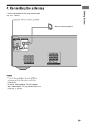
Getting Started 4: Connecting the antennas Connect the supplied AM loop antenna and FM wire antenna. FM wire antenna (supplied) AM loop antenna (supplied) DIGITAL OPTICAL VIDEO 2/ BD IN COAXIAL DVD IN ANTENNA AM L R AUDIO IN AUDIO IN AUDIO IN SA-CD/CD TV SAT RL SUB R L WOOFER SURROUND SPEAKERS Notes • To prevent noise pickup, keep the AM loop antenna away from the receiver and other components. • Be sure to fully extend the FM wire antenna. • After connecting the FM wire antenna, keep it as horizontal as possible. 19US
Getting Started 4: Connecting the antennas Connect the supplied AM loop antenna and FM wire antenna. FM wire antenna (supplied) AM loop antenna (supplied) DIGITAL OPTICAL VIDEO 2/ BD IN COAXIAL DVD IN ANTENNA AM L R AUDIO IN AUDIO IN AUDIO IN SA-CD/CD TV SAT RL SUB R L WOOFER SURROUND SPEAKERS Notes • To prevent noise pickup, keep the AM loop antenna away from the receiver and other components. • Be sure to fully extend the FM wire antenna. • After connecting the FM wire antenna, keep it as horizontal as possible. 19US
Operating Instructions
Page 20
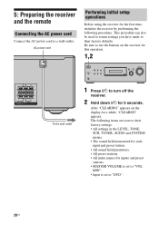
... can also be used to return settings you have made to their factory settings. • All settings in the LEVEL, TONE, SUR, TUNER, AUDIO and SYSTEM menus. • The sound field memorized for each input and preset station. • All sound field parameters. • All preset stations. • All ...; MASTER VOLUME is set to "VOL MIN". • Input is set to use the buttons on the display for this operation. 1,2 RL RL CENTER FRONT SPEAKERS To the wall outlet ?/1 VIDEO 1 IN/ PORTABLE AUDIO IN/ AUTO CAL MIC DIMMER SLEEP 2CH A.F.D. Be sure to "DVD". 20US After "CLEARING" appears ...
... can also be used to return settings you have made to their factory settings. • All settings in the LEVEL, TONE, SUR, TUNER, AUDIO and SYSTEM menus. • The sound field memorized for each input and preset station. • All sound field parameters. • All preset stations. • All ...; MASTER VOLUME is set to "VOL MIN". • Input is set to use the buttons on the display for this operation. 1,2 RL RL CENTER FRONT SPEAKERS To the wall outlet ?/1 VIDEO 1 IN/ PORTABLE AUDIO IN/ AUTO CAL MIC DIMMER SLEEP 2CH A.F.D. Be sure to "DVD". 20US After "CLEARING" appears ...
Operating Instructions
Page 21
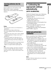
... cause a malfunction. • If you to avoid measurement error. Doing so may be performed correctly. You can also adjust the speaker levels and balance manually. Note The Auto Calibration function does not work when headphones are any obstacles from battery leakage and corrosion. ...damage from the measurement area to perform automatic calibration such as: • Checking the connection between the optimizer microphone and the speakers, the calibration cannot be reset to the effect on your listening position. Tip Under normal conditions, the batteries should last ...
... cause a malfunction. • If you to avoid measurement error. Doing so may be performed correctly. You can also adjust the speaker levels and balance manually. Note The Auto Calibration function does not work when headphones are any obstacles from battery leakage and corrosion. ...damage from the measurement area to perform automatic calibration such as: • Checking the connection between the optimizer microphone and the speakers, the calibration cannot be reset to the effect on your listening position. Tip Under normal conditions, the batteries should last ...
Operating Instructions
Page 23
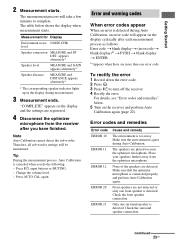
...quiet during measurement. 3 Measurement ends. To rectify the error 1 Record down the error code. 2 Press . 3 Press ?/1 to complete. Place your speakers further away from the receiver after each measurement process as follows: Error code t blank display t (error code t blank display)a) t PUSH t blank display...microphone. Note Auto Calibration cannot detect the sub woofer. Make sure that the optimizer microphone is too noisy. Only one front speaker is detected. Press ?/1, input buttons or MUTING. - Make sure the environment is detected during Auto Calibration, an error code ...
...quiet during measurement. 3 Measurement ends. To rectify the error 1 Record down the error code. 2 Press . 3 Press ?/1 to complete. Place your speakers further away from the receiver after each measurement process as follows: Error code t blank display t (error code t blank display)a) t PUSH t blank display...microphone. Note Auto Calibration cannot detect the sub woofer. Make sure that the optimizer microphone is too noisy. Only one front speaker is detected. Press ?/1, input buttons or MUTING. - Make sure the environment is detected during Auto Calibration, an error code ...
Operating Instructions
Page 24
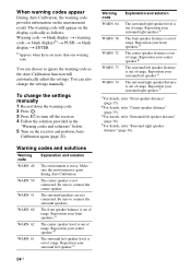
... codes and solutions Warning code Explanation and solution WARN. 40 The environment is quiet during Auto Calibration. Be sure to connect the center speaker. Reposition your front speakers.c) The center speaker distance is out of range. When warning codes appear During Auto Calibration, the warning code provides information on the display cyclically as...
... codes and solutions Warning code Explanation and solution WARN. 40 The environment is quiet during Auto Calibration. Be sure to connect the center speaker. Reposition your front speakers.c) The center speaker distance is out of range. When warning codes appear During Auto Calibration, the warning code provides information on the display cyclically as...
Operating Instructions
Page 25
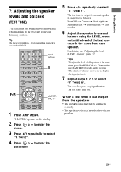
...b to enter the 3 Press V/v repeatedly to select "T. TONE". 4 Press or b to enter the parameter. 5 Press V/v repeatedly to select "T. SYSTEM STANDBY VIDEO 1 VIDEO 2 VIDEO 3 DVD SAT TV SA-CD/CD TUNER Input buttons 2CH A.F.D. TONE Y". For details, see "Adjusting the level (... are shown on the display. 2 Press menu. You can also press any input buttons. Getting Started 7: Adjusting the speaker levels and balance (TEST TONE) You can adjust the speaker levels and balance while listening to select "T. TV CH + PRESET - TONE N". The test tone turns off. MOVIE MUSIC...
...b to enter the 3 Press V/v repeatedly to select "T. TONE". 4 Press or b to enter the parameter. 5 Press V/v repeatedly to select "T. SYSTEM STANDBY VIDEO 1 VIDEO 2 VIDEO 3 DVD SAT TV SA-CD/CD TUNER Input buttons 2CH A.F.D. TONE Y". For details, see "Adjusting the level (... are shown on the display. 2 Press menu. You can also press any input buttons. Getting Started 7: Adjusting the speaker levels and balance (TEST TONE) You can adjust the speaker levels and balance while listening to select "T. TV CH + PRESET - TONE N". The test tone turns off. MOVIE MUSIC...
Operating Instructions
Page 26
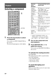
...AUTO CAL MIC jack Blu-ray disc player, etc., connected to the VIDEO 2/BD jack DVD player, etc., connected to select a component. To avoid damaging your speakers Before you do the following. • Press MUTING again. • Increase the volume. • Turn off the receiver, be... TOOLS MUTING F TV VOL MASTER VOL G g f RETURN/EXIT MENU MUTING 3 1 Press the input button to DVD jack Satellite tuner, etc. Playback Selecting a component SYSTEM STANDBY VIDEO 1 VIDEO 2 VIDEO 3 DVD SAT TV SA-CD/CD TUNER 1 2CH A.F.D. MOVIE MUSIC AMP MENU 123 FM MODE 456 7 >10/ - Selected ...
...AUTO CAL MIC jack Blu-ray disc player, etc., connected to the VIDEO 2/BD jack DVD player, etc., connected to select a component. To avoid damaging your speakers Before you do the following. • Press MUTING again. • Increase the volume. • Turn off the receiver, be... TOOLS MUTING F TV VOL MASTER VOL G g f RETURN/EXIT MENU MUTING 3 1 Press the input button to DVD jack Satellite tuner, etc. Playback Selecting a component SYSTEM STANDBY VIDEO 1 VIDEO 2 VIDEO 3 DVD SAT TV SA-CD/CD TUNER 1 2CH A.F.D. MOVIE MUSIC AMP MENU 123 FM MODE 456 7 >10/ - Selected ...


