The Sony Guide to Home Theater
Page 41
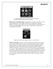
... trace the polarity down the entire length of the speaker cable will be red, have a stripe or have ridges on each speaker. The Sony Guide to your A/V receiver. ƒ Speaker Connections. Dedicated speaker wires are immune from electromagnetic interference. For the best sound, observe the "polarity" by side. Speaker cables are usually coded to help you won't need...
... trace the polarity down the entire length of the speaker cable will be red, have a stripe or have ridges on each speaker. The Sony Guide to your A/V receiver. ƒ Speaker Connections. Dedicated speaker wires are immune from electromagnetic interference. For the best sound, observe the "polarity" by side. Speaker cables are usually coded to help you won't need...

Operating Instructions
Page 18
... battery with an old one. • Do not drop any foreign object into the Remote You can begin enjoying your new system right away. Connection and Installation (card) (1) Inserting Batteries into the remote casing, particularly when replacing the batteries. •... sensor to avoid possible damage from the sun or lighting apparatus. Unpacking Check that you have the following items: • Speakers (5) • Sub woofer (1) • AM loop antenna (1) • FM wire antenna (1) • Speaker cords (3.5 m × 3, 5 m × 1, 10 m × 2) (12 ft. × 3, 17 ft. × 1, 33 ft...
... battery with an old one. • Do not drop any foreign object into the Remote You can begin enjoying your new system right away. Connection and Installation (card) (1) Inserting Batteries into the remote casing, particularly when replacing the batteries. •... sensor to avoid possible damage from the sun or lighting apparatus. Unpacking Check that you have the following items: • Speakers (5) • Sub woofer (1) • AM loop antenna (1) • FM wire antenna (1) • Speaker cords (3.5 m × 3, 5 m × 1, 10 m × 2) (12 ft. × 3, 17 ft. × 1, 33 ft...

Operating Instructions
Page 21
...the speakers Short-circuiting of the speakers may result. Stripped cords are touching each speaker cord does not touch another speaker terminal or the bare wire of the speaker cord Stripped speaker cord is output from a speaker while outputting a test tone, or a test tone is touching another speaker ...surface may damage the system. For details on the components: 3 to 3, and # to follow these precautions when connecting the speakers. Getting Started Note on placing speakers Use caution when placing the unit or speakers on surfaces that all the components, speakers, and AC power ...
...the speakers Short-circuiting of the speakers may result. Stripped cords are touching each speaker cord does not touch another speaker terminal or the bare wire of the speaker cord Stripped speaker cord is output from a speaker while outputting a test tone, or a test tone is touching another speaker ...surface may damage the system. For details on the components: 3 to 3, and # to follow these precautions when connecting the speakers. Getting Started Note on placing speakers Use caution when placing the unit or speakers on surfaces that all the components, speakers, and AC power ...

Operating Instructions
Page 22
...Antenna Hookups Connect the supplied AM and FM antennas to listen to fully extend the FM wire antenna. • After connecting the FM wire antenna, keep the AM loop antenna away from the system and other components. • Be sure to the radio. Terminals for connecting the antennas ...Connect the AM loop antenna FM wire antenna To the AM terminals FM 75Ω COAXIAL jack AM loop antenna ANTENNA AM 120V 220V y VOLTAGE SELECTOR Y L L PB/CB R R PR/CR AUDIO IN AUDIO IN VIDEO IN VIDEO OUT COMPONENT TV VIDEO MONITOR VIDEO OUT SPEAKERS F-RONT+R C-ENTE+R F-RONT+L + ...
...Antenna Hookups Connect the supplied AM and FM antennas to listen to fully extend the FM wire antenna. • After connecting the FM wire antenna, keep the AM loop antenna away from the system and other components. • Be sure to the radio. Terminals for connecting the antennas ...Connect the AM loop antenna FM wire antenna To the AM terminals FM 75Ω COAXIAL jack AM loop antenna ANTENNA AM 120V 220V y VOLTAGE SELECTOR Y L L PB/CB R R PR/CR AUDIO IN AUDIO IN VIDEO IN VIDEO OUT COMPONENT TV VIDEO MONITOR VIDEO OUT SPEAKERS F-RONT+R C-ENTE+R F-RONT+L + ...
Operating Instructions
Page 79
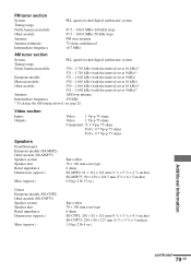
...× 124.5 mm (35/8 × 6 × 5 inches) 0.8 kg (1 lb 13 oz.) Center European models (SS-CNP2) Other models (SS-CNP75) Speaker system Speaker unit Rated impedance Dimensions (approx.) Mass (approx.) Bass reflex 70 × 100 mm cone type 6 ohms SS-CNP2: 230 × 81 × 121 mm (9... terminals Intermediate frequency PLL quartz-locked digital synthesizer system 87.5 - 108.0 MHz (100 kHz step) 87.5 - 108.0 MHz (50 kHz step) FM wire antenna 75 ohms, unbalanced 10.7 MHz AM tuner section System PLL quartz-locked digital synthesizer system Tuning range North American models: 530 - 1,...
...× 124.5 mm (35/8 × 6 × 5 inches) 0.8 kg (1 lb 13 oz.) Center European models (SS-CNP2) Other models (SS-CNP75) Speaker system Speaker unit Rated impedance Dimensions (approx.) Mass (approx.) Bass reflex 70 × 100 mm cone type 6 ohms SS-CNP2: 230 × 81 × 121 mm (9... terminals Intermediate frequency PLL quartz-locked digital synthesizer system 87.5 - 108.0 MHz (100 kHz step) 87.5 - 108.0 MHz (50 kHz step) FM wire antenna 75 ohms, unbalanced 10.7 MHz AM tuner section System PLL quartz-locked digital synthesizer system Tuning range North American models: 530 - 1,...


