Operating Instructions
Page 2
... energy and, if not installed and used in a residential installation. Increase the separation between the equipment and receiver. - Don't throw away batteries with the limits for help. If this system so that interference will not occur in the event of trouble. Reorient or relocate the... receiving antenna. - To prevent fire, do not place objects filled with newspapers, table-cloths, curtains, etc. Install this equipment...
... energy and, if not installed and used in a residential installation. Increase the separation between the equipment and receiver. - Don't throw away batteries with the limits for help. If this system so that interference will not occur in the event of trouble. Reorient or relocate the... receiving antenna. - To prevent fire, do not place objects filled with newspapers, table-cloths, curtains, etc. Install this equipment...
Operating Instructions
Page 3
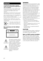
... related logos are clearly indicated in this manual are for receiver operation. The HT-7100DH consists of area code AA only". Sub woofer SA-WP780 • The instructions in the text, for example, "Models of : • Receiver STR-K7100 • DVD player DVP-NC85H • Speaker system - You can also use the controls on the...
... related logos are clearly indicated in this manual are for receiver operation. The HT-7100DH consists of area code AA only". Sub woofer SA-WP780 • The instructions in the text, for example, "Models of : • Receiver STR-K7100 • DVD player DVP-NC85H • Speaker system - You can also use the controls on the...
Operating Instructions
Page 4
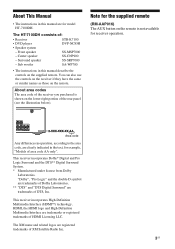
...Installing speakers 14 2: Connecting speakers 16 3a: Connecting the audio components ........17 3b: Connecting the video components ........18 4: Connecting the antennas 26 5: Preparing the receiver and the remote.....27 6: Selecting the speaker system 28 7: Calibrating the appropriate settings automatically (AUTO CALIBRATION 29 8:...PORT (DMPORT 63 Listening to the XM Radio 56 Presetting XM Radio stations 60 Playback Selecting a component 34 Listening/Watching a component 36 Amplifier Operations Navigating through menus 38 Adjusting the level (LEVEL menu 41 Adjusting the tone (TONE...
...Installing speakers 14 2: Connecting speakers 16 3a: Connecting the audio components ........17 3b: Connecting the video components ........18 4: Connecting the antennas 26 5: Preparing the receiver and the remote.....27 6: Selecting the speaker system 28 7: Calibrating the appropriate settings automatically (AUTO CALIBRATION 29 8:...PORT (DMPORT 63 Listening to the XM Radio 56 Presetting XM Radio stations 60 Playback Selecting a component 34 Listening/Watching a component 36 Amplifier Operations Navigating through menus 38 Adjusting the level (LEVEL menu 41 Adjusting the tone (TONE...

Operating Instructions
Page 5
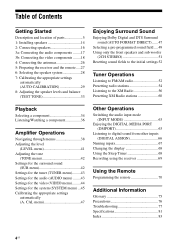
... 33, 34, 36, 37). Press to select the input mode when the same components are connected to activate the Auto Calibration function (page 29). Press to both digital and analog jacks (page 63). Receives signals from remote commander. Name F DISPLAY G INPUT MODE H MASTER VOLUME I MUTING...information displayed on the display (page 68). continued 5US Press to turn the receiver on /standby) B SPEAKERS (OFF/A/B/A+B) C Display D MULTI CHANNEL DECODING lamp E Remote sensor Function Press to select the speaker system (page 28). Lights up when multi channel audio is decoded (page 37)....
... 33, 34, 36, 37). Press to select the input mode when the same components are connected to activate the Auto Calibration function (page 29). Press to both digital and analog jacks (page 63). Receives signals from remote commander. Name F DISPLAY G INPUT MODE H MASTER VOLUME I MUTING...information displayed on the display (page 68). continued 5US Press to turn the receiver on /standby) B SPEAKERS (OFF/A/B/A+B) C Display D MULTI CHANNEL DECODING lamp E Remote sensor Function Press to select the speaker system (page 28). Lights up when multi channel audio is decoded (page 37)....
Operating Instructions
Page 7
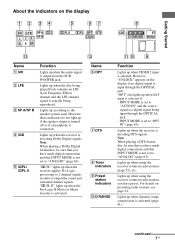
...jack. Name F OPT G DTS H Tuner indicators I Preset station indicators J D.RANGE Function Lights up according to the speaker system used. "OPT" also lights up when using the receiver to tune in radio stations you have preset. INPUT MODE is set to "ANALOG" (page 63). Lights up when SAT...radio stations (page 52), etc. Lights up when the audio signal is decoding DTS signals. continued 7US PL II" lights up when the receiver is activated. "; Getting Started About the indicators on presetting radio stations, see page 54. Note When playing a Dolby Digital format disc, ...
...jack. Name F OPT G DTS H Tuner indicators I Preset station indicators J D.RANGE Function Lights up according to the speaker system used. "OPT" also lights up when using the receiver to tune in radio stations you have preset. INPUT MODE is set to "ANALOG" (page 63). Lights up when SAT...radio stations (page 52), etc. Lights up when the audio signal is decoding DTS signals. continued 7US PL II" lights up when the receiver is activated. "; Getting Started About the indicators on presetting radio stations, see page 54. Note When playing a Dolby Digital format disc, ...

Operating Instructions
Page 8
... Left Front Right Center (monaural) Surround Left Surround Right Surround (monaural or the surround components obtained by Pro Logic processing) Example: Recording format (Front/ Surround): 3/2.1 Sound Field: A.F.D. The boxes around the letters vary to show how the receiver downmixes the source sound. Name K MEMORY L COAX M Playback channel indicators L R C SL SR S Function Lights...
... Left Front Right Center (monaural) Surround Left Surround Right Surround (monaural or the surround components obtained by Pro Logic processing) Example: Recording format (Front/ Surround): 3/2.1 Sound Field: A.F.D. The boxes around the letters vary to show how the receiver downmixes the source sound. Name K MEMORY L COAX M Playback channel indicators L R C SL SR S Function Lights...
Operating Instructions
Page 10
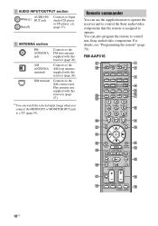
... wa G g w; F ANTENNA section FM ANTENNA jack Connects to the FM wire antenna supplied with this receiver) (page 57). XM terminal Connects to control non-Sony audio/video components. a)You can watch the selected input image when you connect the HDMI OUT or MONITOR OUT jack to operate... remote to operate the receiver and to control the Sony audio/video components that the remote is assigned to a TV (page 19). RM-AAP016 wj wh TV RM SET UP AV ?/1 ? / 1 SYSTEM STANDBY VIDEO 1 VIDEO 2 VIDEO 3 DVD SAT TV SA-CD/CD TUNER 1 2 3 AUX DMPORT RECEIVER 4 2CH A.F.D. ql qk...
... wa G g w; F ANTENNA section FM ANTENNA jack Connects to the FM wire antenna supplied with this receiver) (page 57). XM terminal Connects to control non-Sony audio/video components. a)You can watch the selected input image when you connect the HDMI OUT or MONITOR OUT jack to operate... remote to operate the receiver and to control the Sony audio/video components that the remote is assigned to a TV (page 19). RM-AAP016 wj wh TV RM SET UP AV ?/1 ? / 1 SYSTEM STANDBY VIDEO 1 VIDEO 2 VIDEO 3 DVD SAT TV SA-CD/CD TUNER 1 2 3 AUX DMPORT RECEIVER 4 2CH A.F.D. ql qk...
Operating Instructions
Page 11
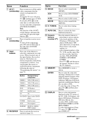
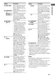
... When you want to use. The buttons are factory assigned to select the TV channels. TUNING Press to enter direct tuning mode. D RECEIVER Button Assigned Sony component VIDEO 1 VCR (VTR mode 3) VIDEO 2 VCR (VTR mode 2) VIDEO 3 VCR (VTR mode 1) DVD DVD player SAT Satellite ...to select A.F.D. select track numbers of Sony TV, press TV (Z) and then press ENTER. ray disc recorder, hard disc recorder, PSX, DVD/VHS COMBO or DVD/HDD COMBO. Name Function A AV ?/1 Press to turn on or off the receiver and other components (SYSTEM STANDBY). I MEMORY Press MEMORY to...
... When you want to use. The buttons are factory assigned to select the TV channels. TUNING Press to enter direct tuning mode. D RECEIVER Button Assigned Sony component VIDEO 1 VCR (VTR mode 3) VIDEO 2 VCR (VTR mode 2) VIDEO 3 VCR (VTR mode 1) DVD DVD player SAT Satellite ...to select A.F.D. select track numbers of Sony TV, press TV (Z) and then press ENTER. ray disc recorder, hard disc recorder, PSX, DVD/VHS COMBO or DVD/HDD COMBO. Name Function A AV ?/1 Press to turn on or off the receiver and other components (SYSTEM STANDBY). I MEMORY Press MEMORY to...
Operating Instructions
Page 12
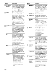
...To display the menus of the VCR, DAT deck, or tape deck. fast forward/rewind of Sony TV, press TV (Z) and then press MENU. TUNING +/- Press TV (Z) and then press ...ray disc recorder, PSX, DVD/VHS COMBO, or DVD/HDD COMBO. (Also starts recording with components in the forward/ backward direction of the receiver, VCR, DVD player, satellite tuner, Blu-ray disc recorder, PSX, DVD/VHS COMBO or ...MENU Press to stop playback of the DVD player on the TV screen. DVD MENU Press to start playback of Sony TV, press TV (Z) and then press OPTIONS TOOLS. Press TV (Z) and then press TV VOL to mute ...
...To display the menus of the VCR, DAT deck, or tape deck. fast forward/rewind of Sony TV, press TV (Z) and then press MENU. TUNING +/- Press TV (Z) and then press ...ray disc recorder, PSX, DVD/VHS COMBO, or DVD/HDD COMBO. (Also starts recording with components in the forward/ backward direction of the receiver, VCR, DVD player, satellite tuner, Blu-ray disc recorder, PSX, DVD/VHS COMBO or ...MENU Press to stop playback of the DVD player on the TV screen. DVD MENU Press to start playback of Sony TV, press TV (Z) and then press OPTIONS TOOLS. Press TV (Z) and then press TV VOL to mute ...
Operating Instructions
Page 13
... numeric button of Sony TV, press TV (Z) and then press RETURN/EXIT O. It changes the remote key function to select the category mode for receiver operation. 13US Getting Started Use the tactile dots as an example only. Therefore, depending on the component, the above explanation... is also available for receiver operation, press V/v/B/b to serve as references when operating the receiver. Function Press to - Press to skip disc of the TV, DVD player, Satellite...
... numeric button of Sony TV, press TV (Z) and then press RETURN/EXIT O. It changes the remote key function to select the category mode for receiver operation. 13US Getting Started Use the tactile dots as an example only. Therefore, depending on the component, the above explanation... is also available for receiver operation, press V/v/B/b to serve as references when operating the receiver. Function Press to - Press to skip disc of the TV, DVD player, Satellite...
Operating Instructions
Page 18
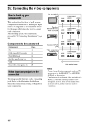
... 26). After hooking up your components, proceed to a TV through the receiver. MOVIE MUSIC AUTO CAL MUTING Receiver INPUT jack Video component OUTPUT jack HDMI HDMI COMPONENT VIDEO VIDEO COMPONENT VIDEO VIDEO High quality image Notes • Connect image display components such as a TV or a projector to connect each component. Component to be connected Component Page TV 19 DVD player...
... 26). After hooking up your components, proceed to a TV through the receiver. MOVIE MUSIC AUTO CAL MUTING Receiver INPUT jack Video component OUTPUT jack HDMI HDMI COMPONENT VIDEO VIDEO COMPONENT VIDEO VIDEO High quality image Notes • Connect image display components such as a TV or a projector to connect each component. Component to be connected Component Page TV 19 DVD player...

Operating Instructions
Page 19
... you connect the MONITOR OUT jack to a TV. • To output the sound of the TV from a visual component connected to this receiver and the menu of the receiver is not turned on, neither video nor audio is not necessary to connect all the cables. Audio signals TV Video signals...cord (not supplied) B Video cord (not supplied) C Component video cord (not supplied) Notes • Connect image display components such as a TV or a projector to the MONITOR OUT jack on the receiver. • Turn on the receiver when the video and audio of a playback component are being output to the TV IN jack of...
... you connect the MONITOR OUT jack to a TV. • To output the sound of the TV from a visual component connected to this receiver and the menu of the receiver is not turned on, neither video nor audio is not necessary to connect all the cables. Audio signals TV Video signals...cord (not supplied) B Video cord (not supplied) C Component video cord (not supplied) Notes • Connect image display components such as a TV or a projector to the MONITOR OUT jack on the receiver. • Turn on the receiver when the video and audio of a playback component are being output to the TV IN jack of...
Operating Instructions
Page 21
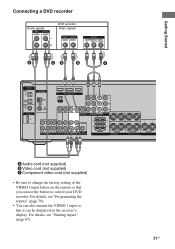
... HDMI Y XM PB/CB PR/CR VIDEO IN VIDEO IN VIDEO OUT VIDEO IN VIDEO OUT SAT IN DVD IN VIDEO 1 IN MONITOR OUT L MONITOR COMPONENT VIDEO R L L L L L AUDIO OUT R R OUT IN IN SA-CD/CD/CD-R TV R AUDIO IN AUDIO IN SAT DVD R AUDIO OUT AUDIO IN VIDEO...FRONT B R FRONT A SPEAKERS L R SURROUND CENTER A Audio cord (not supplied) B Video cord (not supplied) C Component video cord (not supplied) • Be sure to change the factory setting of the VIDEO 1 input button on the receiver's display. For details, see "Programming the remote" (page 70). • You can also rename the VIDEO...
... HDMI Y XM PB/CB PR/CR VIDEO IN VIDEO IN VIDEO OUT VIDEO IN VIDEO OUT SAT IN DVD IN VIDEO 1 IN MONITOR OUT L MONITOR COMPONENT VIDEO R L L L L L AUDIO OUT R R OUT IN IN SA-CD/CD/CD-R TV R AUDIO IN AUDIO IN SAT DVD R AUDIO OUT AUDIO IN VIDEO...FRONT B R FRONT A SPEAKERS L R SURROUND CENTER A Audio cord (not supplied) B Video cord (not supplied) C Component video cord (not supplied) • Be sure to change the factory setting of the VIDEO 1 input button on the receiver's display. For details, see "Programming the remote" (page 70). • You can also rename the VIDEO...
Operating Instructions
Page 22
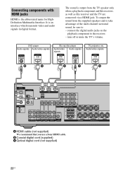
... WOOFER FRONT B R FRONT A SPEAKERS L R SURROUND CENTER A HDMI cable (not supplied) We recommend that you use a Sony HDMI cable. connect the digital audio jacks on the playback component to - B Coaxial digital cord (supplied) C Optical digital cord (not supplied) 22US The sound is the abbreviated name for .../video signals Audio signals TV, projector, etc. To output the sound from the TV speaker only when a playback component and this receiver, as well as this receiver and the TV are connected via a HDMI jack. It is an interface which transmits video and audio signals in ...
... WOOFER FRONT B R FRONT A SPEAKERS L R SURROUND CENTER A HDMI cable (not supplied) We recommend that you use a Sony HDMI cable. connect the digital audio jacks on the playback component to - B Coaxial digital cord (supplied) C Optical digital cord (not supplied) 22US The sound is the abbreviated name for .../video signals Audio signals TV, projector, etc. To output the sound from the TV speaker only when a playback component and this receiver, as well as this receiver and the TV are connected via a HDMI jack. It is an interface which transmits video and audio signals in ...
Operating Instructions
Page 23
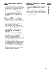
... not turned on, neither video nor audio is poor or the sound does not come out of a component connected via the receiver. The input video signals cannot be output from the VIDEO OUT or MONITOR OUT jacks. • Refer to the HDMI IN jack can only be ... compatible with 32 kHz, 44.1 kHz, 48 kHz, and 96 kHz sampling frequencies. 23US Notes on HDMI connections • This receiver may be restricted by the connected component. Getting Started If you connect a Blu-ray disc player • Be sure to change the factory setting of the VIDEO 2 input button on the...
... not turned on, neither video nor audio is poor or the sound does not come out of a component connected via the receiver. The input video signals cannot be output from the VIDEO OUT or MONITOR OUT jacks. • Refer to the HDMI IN jack can only be ... compatible with 32 kHz, 44.1 kHz, 48 kHz, and 96 kHz sampling frequencies. 23US Notes on HDMI connections • This receiver may be restricted by the connected component. Getting Started If you connect a Blu-ray disc player • Be sure to change the factory setting of the VIDEO 2 input button on the...

Operating Instructions
Page 26
... HDMI Y XM PB/CB PR/CR VIDEO IN VIDEO IN VIDEO OUT VIDEO IN VIDEO OUT SAT IN DVD IN VIDEO 1 IN MONITOR OUT L MONITOR COMPONENT VIDEO R L L L L L AUDIO OUT R R OUT IN IN SA-CD/CD/CD-R TV R AUDIO IN AUDIO IN SAT DVD R AUDIO OUT AUDIO IN VIDEO 1 SUB ...R FRONT A SPEAKERS L R SURROUND CENTER * The shape of the connector varies depending on the area code of this receiver. Notes • To prevent noise pickup, keep the AM loop antenna away from the receiver and other components. • Be sure to fully extend the FM wire antenna. • After connecting the FM wire antenna...
... HDMI Y XM PB/CB PR/CR VIDEO IN VIDEO IN VIDEO OUT VIDEO IN VIDEO OUT SAT IN DVD IN VIDEO 1 IN MONITOR OUT L MONITOR COMPONENT VIDEO R L L L L L AUDIO OUT R R OUT IN IN SA-CD/CD/CD-R TV R AUDIO IN AUDIO IN SAT DVD R AUDIO OUT AUDIO IN VIDEO 1 SUB ...R FRONT A SPEAKERS L R SURROUND CENTER * The shape of the connector varies depending on the area code of this receiver. Notes • To prevent noise pickup, keep the AM loop antenna away from the receiver and other components. • Be sure to fully extend the FM wire antenna. • After connecting the FM wire antenna...
Operating Instructions
Page 27
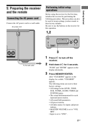
...L AUDIO R MULTI CHANNEL DECODING DISPLAY INPUT MODE INPUT SELECTOR MASTER VOLUME MEMORY/ ENTER TUNING MODE TUNING 2CH A.F.D. Getting Started 5: Preparing the receiver and the remote Connecting the AC power cord Connect the AC power cord to their factory settings. • All settings in the LEVEL, ...TONE, SUR, TUNER, AUDIO, VIDEO and SYSTEM menus. • The sound field memorized for each input and preset station. • All sound field parameters. • All preset stations. &#...
...L AUDIO R MULTI CHANNEL DECODING DISPLAY INPUT MODE INPUT SELECTOR MASTER VOLUME MEMORY/ ENTER TUNING MODE TUNING 2CH A.F.D. Getting Started 5: Preparing the receiver and the remote Connecting the AC power cord Connect the AC power cord to their factory settings. • All settings in the LEVEL, ...TONE, SUR, TUNER, AUDIO, VIDEO and SYSTEM menus. • The sound field memorized for each input and preset station. • All sound field parameters. • All preset stations. &#...
Operating Instructions
Page 28
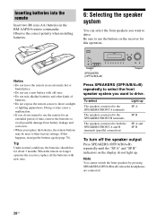
...B SP A and SP B To turn off the speaker output Press SPEAKERS (OFF/A/B/A+B) repeatedly until the "SP A" and "SP B" indicators on the receiver for this happens, reassign the buttons again (page 70). Inserting batteries into the remote Insert two R6 (size-AA) batteries in an extremely hot or... leakage and corrosion. • When you want to drive. Be sure to use a new battery with new ones. 6: Selecting the speaker system You can select the front speakers you want to direct sunlight or lighting apparatuses. Tip Under normal conditions, the batteries should last for about 3...
...B SP A and SP B To turn off the speaker output Press SPEAKERS (OFF/A/B/A+B) repeatedly until the "SP A" and "SP B" indicators on the receiver for this happens, reassign the buttons again (page 70). Inserting batteries into the remote Insert two R6 (size-AA) batteries in an extremely hot or... leakage and corrosion. • When you want to drive. Be sure to use a new battery with new ones. 6: Selecting the speaker system You can select the front speakers you want to direct sunlight or lighting apparatuses. Tip Under normal conditions, the batteries should last for about 3...
Operating Instructions
Page 29
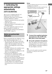
... D.C.A.C. (Digital Cinema Auto Calibration) Technology which allows you to perform automatic calibration as your listening position. Doing so may damage the receiver and the microphone. • During the calibration, the sound that the optimizer microphone remains at your neighborhood. • Perform the ...Auto Calibration, it will get a more accurate measurement. 29US Use a stool or tripod so that comes out of each speaker and the receiver. • Adjust the speaker level. • Measure the distance of the speakers is used for the supplied optimizer microphone only. Do not...
... D.C.A.C. (Digital Cinema Auto Calibration) Technology which allows you to perform automatic calibration as your listening position. Doing so may damage the receiver and the microphone. • During the calibration, the sound that the optimizer microphone remains at your neighborhood. • Perform the ...Auto Calibration, it will get a more accurate measurement. 29US Use a stool or tripod so that comes out of each speaker and the receiver. • Adjust the speaker level. • Measure the distance of the speakers is used for the supplied optimizer microphone only. Do not...

Operating Instructions
Page 30
...MUSIC CATEGORY SLEEP MODE D.TUNING AUTO CAL 123 456 7 -/-- When measurement ends, "COMPLETE" appears on the display. Stand some distance from the receiver. Change the volume level. - CLEAR >10 GUIDE 89 0/10 F ENTER MEMORY DISPLAY G g MASTER VOL +/- TUNING + m M DISC ... speakers during measurement. - Performing Auto Calibration Input buttons ? / 1 TV RM SET UP AV ?/1 SYSTEM STANDBY VIDEO 1 VIDEO 2 VIDEO 3 DVD SAT TV SA-CD/CD TUNER AUX DMPORT RECEIVER 2CH A.F.D. Tips • When Auto Calibration starts: - Avoid making noise to get a more accurate ...
...MUSIC CATEGORY SLEEP MODE D.TUNING AUTO CAL 123 456 7 -/-- When measurement ends, "COMPLETE" appears on the display. Stand some distance from the receiver. Change the volume level. - CLEAR >10 GUIDE 89 0/10 F ENTER MEMORY DISPLAY G g MASTER VOL +/- TUNING + m M DISC ... speakers during measurement. - Performing Auto Calibration Input buttons ? / 1 TV RM SET UP AV ?/1 SYSTEM STANDBY VIDEO 1 VIDEO 2 VIDEO 3 DVD SAT TV SA-CD/CD TUNER AUX DMPORT RECEIVER 2CH A.F.D. Tips • When Auto Calibration starts: - Avoid making noise to get a more accurate ...


